Auditory Motion lab technical info: Difference between revisions
| (18 intermediate revisions by the same user not shown) | |||
| Line 16: | Line 16: | ||
*Floor: anti-fatigue rubber floor mat with holes | *Floor: anti-fatigue rubber floor mat with holes | ||
see [[Acoustic Materials]] | see [[Acoustic Materials]] | ||
===Coordinates=== | |||
The orientation of the coordinates is determined by the position of the head of the subject looking to the arm speaker in its default position (= facing the wall speakers). | |||
* Frontal: Front is Y+, Back is Y- | |||
* Horizontal: Right is X+, Left is X- | |||
* Vertical: Top is Z+, Bottom is Z- | |||
For Double Polar coordinates see [[Coordinate systems]] | |||
==Computer== | ==Computer== | ||
| Line 21: | Line 29: | ||
A windows computer with MATLAB, RPvdsEx and zBUSmon. The computer has an optical interface card (PO5e) for communication with the Tucker Davis equipment via the Optibit optical bus (FO5) at the back of the rack. The working of the optical bus can be monitored by the program zBUSmon program from TDT. This program has also some control functions for the optical bus. It shows all the connected zBus chassis and the TDT devices that are installed in each chassis. It also shows the version number of the installed firmware on the devices. | A windows computer with MATLAB, RPvdsEx and zBUSmon. The computer has an optical interface card (PO5e) for communication with the Tucker Davis equipment via the Optibit optical bus (FO5) at the back of the rack. The working of the optical bus can be monitored by the program zBUSmon program from TDT. This program has also some control functions for the optical bus. It shows all the connected zBus chassis and the TDT devices that are installed in each chassis. It also shows the version number of the installed firmware on the devices. | ||
==Software== | ==Software== | ||
%todo | |||
===<name of the program>=== | ===<name of the program>=== | ||
| Line 27: | Line 35: | ||
===RPvdsX software=== | ===RPvdsX software=== | ||
The BIOX sofware can be found | The BIOX sofware can be found [https://gitlab.science.ru.nl/marcw/biofysica/-/tree/master/experiment/biox_rz6?ref_type=heads here] in Gitlab. | ||
==Electronics rack== | ==Electronics rack== | ||
| Line 42: | Line 50: | ||
*Robot arm manual user interface | *Robot arm manual user interface | ||
*Digital Eventrecorder | *Digital Eventrecorder | ||
*Oscilloscope | *[[Tektronix TBS 1064|Oscilloscope]] | ||
*Field coil generator (amplifier) | *Field coil generator (amplifier) | ||
*Femto Lock-in amplifier module | *Femto Lock-in amplifier module | ||
| Line 79: | Line 87: | ||
[[File:xxxxxxxxx.png|thumb|Scheme of trigger system]] | [[File:xxxxxxxxx.png|thumb|Scheme of trigger system]] | ||
===Parts=== | ===Parts=== | ||
*Pushbutton (passive switch, normally open) | *Pushbutton (passive switch, normally open) | ||
*RZ6 Buttonbox (4 passive switches, normally open; 4 led indicators) | *RZ6 Buttonbox (4 passive switches, normally open; 4 led indicators) | ||
*[[Digital event recorder]] | *[[8 channel digital event recorder|Digital event recorder (LSLDER03)]] | ||
==Head Tracking System== | ==Head Tracking System== | ||
See [[EM Field Head Tracking System specifications]] | |||
[[File:RobotLab_Lockin_Settings.JPEG|300px|thumb|right|Lock-in amplifier settings]] | |||
[[File: | Three Femto LIA-BV-150-H Lock-in amplifiers are used in order to separate the Frontal, Horizontal and Vertical signals from the pick-up coil. Each Lock-in amplifier has a Sinus Oscillator Module (SOM-1) that is used both as Field Modulation Signal and as Reference Signal. The Lock-in amplifier settings are set at the front of the device (see picture), except for the modulation/reference frequency which is set inside on the SOM-board. | ||
{| class="wikitable" | {| class="wikitable" | ||
! | ! Setting | ||
! | ! Frontal (Red) | ||
! | ! Vertical (Blue) | ||
! | ! Horizontal (Yellow) | ||
|- | |||
| Frequency | |||
| 45kHz | |||
| 55kHz | |||
| 65kHz | |||
|- | |||
| Time constant | |||
| A | |||
| A | |||
| A | |||
|- | |||
| Sensitivity | |||
| 1 | |||
| 1 | |||
| 1 | |||
|- | |||
| Phase Course | |||
| 8 | |||
| 0 | |||
| 8 | |||
|- | |||
| Phase Fine | |||
| 4 | |||
| D | |||
| 6 | |||
|- | |||
| Dynamic Reserve | |||
| L | |||
| L | |||
| L | |||
|- | |- | ||
| | | Mode | ||
| | | 1f | ||
| | | 1f | ||
| | | 1f | ||
|- | |- | ||
| | | PLL | ||
| | | S | ||
| | | S | ||
| | | S | ||
|- | |- | ||
| | | Reference Threshold | ||
| | | 0V | ||
| | | 0V | ||
| | | 0V | ||
|} | |} | ||
Latest revision as of 11:21, 16 February 2024
Introduction
The Auditory Motion Lab is a facility designed for experiments involving moving sound sources. The lab features a soundproof booth, ensuring an isolated testing environment. At the heart of the lab is a two-axis robot arm suspended from the ceiling. This arm is equipped with a high-fidelity speaker capable of moving at a fixed distance around the subject's head. The centrally placed chair, which can rotate on its vertical axis, allows subjects to experience sound from various angles. Head movements are tracked using a 3-axis electromagnetic field (EMF) head tracking system. Additionally, wall-mounted speakers facing the subject provide ambient or background sounds to enrich the experimental scenarios.
Booth
- Dimensions: LxWxH = 420x300x285cm
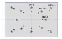
The sound booth is an acoustically isolated room with sound absorbing materials on all walls and the floor to reduce reverberation. A 2.4 m diameter quarter sphere build of a metal structure holds 43 small passive speakers. The speakers also contain two color LED's. In the center of the booth there is a chair for a subject. The chair is placed in a way that the head of the subject is right in center of the sphere. Large coils are embedded in the walls of the sound booth. The coils make a box of about 2.5 m x 2.3 m x 2.8 m. These coils are used for head movement detection.
An infrared camera is installed in the booth. The experimenter has a monitor from which he/she can see the inside of the booth. The camera looks down on the back of the subject.
Acoustics
The Booth is acoustically isolated from its environment. The walls and corners are covered by acoustic materials.
- Walls: egg box type soundproofing foam
- Floor: anti-fatigue rubber floor mat with holes
Coordinates
The orientation of the coordinates is determined by the position of the head of the subject looking to the arm speaker in its default position (= facing the wall speakers).
- Frontal: Front is Y+, Back is Y-
- Horizontal: Right is X+, Left is X-
- Vertical: Top is Z+, Bottom is Z-
For Double Polar coordinates see Coordinate systems
Computer
A windows computer with MATLAB, RPvdsEx and zBUSmon. The computer has an optical interface card (PO5e) for communication with the Tucker Davis equipment via the Optibit optical bus (FO5) at the back of the rack. The working of the optical bus can be monitored by the program zBUSmon program from TDT. This program has also some control functions for the optical bus. It shows all the connected zBus chassis and the TDT devices that are installed in each chassis. It also shows the version number of the installed firmware on the devices.
Software
%todo
<name of the program>
The programming of the RZ6 is based on the BIOX toolbox.
RPvdsX software
The BIOX sofware can be found here in Gitlab.
Electronics rack

From top to bottom:
- Patch Panel Audio Wall
- 3x quad-channel audio amplifier
- 24 channel Motu sound processor
- Zbus caddy: Left=empty; Right=Patch Panel Arm Speakers
- RZ6 MUlti I/O Processor
- Patch Panel RZ6 Digital-I/O
- Zbus caddy: Left=empty; Right= 6 channel ADC
- Frame: Left=empty; Right= Patch panel for 6 channel ADC
- Robot arm manual user interface
- Digital Eventrecorder
- Oscilloscope
- Field coil generator (amplifier)
- Femto Lock-in amplifier module
Sound system
There is a primary sound system with speakers on the robot arm and a secondary sound system with speakers on the wall. The purpose of the primary system is to provide moving sound stimuli. the purpose of the secondary sound system is to provide background sounds or noise.
Primary sound system

The primary sound system consists of a programmable sound processor (RZ6) with two analog outputs (Out-A and Out-B. The RZ6 generates a sound signal that travels to a patch panel inside the booth and from there to two speakers on the robot arm.
Speaker specifications:
- Sensitivity: 86 dB SPL (@2.83 Vrms input)
- Frequency response: 150 Hz-20 kHz
- Impedance: 8 Ohms
- H x W x D: 78 x 78 x 85 mm
- Weight: 0.43 kg
The speakers are connected via 2 lead wires for the sound and 3 lead wires for the LED's.
Secondary sound system
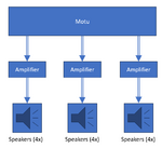
The secondary sound system consists of a 24 channel Motu 24Ao USB audio sound processor, three 4 channel Behringer EPQ304 audio amplifiers, and 12 wall mounted Cambridge audio Minx Min12 speakers. The purpose of the speaker wall is to provide background noise to the moving sounds produced by the speaker(s) on the arm.
LED system

The LED system consist of Red/Green LEDs mounted in the center of the arm speakers (2x) as well as the wall speakers (12x). The LEDs are controlled by the LED controller box (ID: DCN-LED12) which is mounted on the front facing wall inside the booth. The controller has an ethernet interface for the configuration settings and is triggered by the
Specifications Red/Green LEDs
Trigger/Timing system
Parts
- Pushbutton (passive switch, normally open)
- RZ6 Buttonbox (4 passive switches, normally open; 4 led indicators)
- Digital event recorder (LSLDER03)
Head Tracking System
See EM Field Head Tracking System specifications

Three Femto LIA-BV-150-H Lock-in amplifiers are used in order to separate the Frontal, Horizontal and Vertical signals from the pick-up coil. Each Lock-in amplifier has a Sinus Oscillator Module (SOM-1) that is used both as Field Modulation Signal and as Reference Signal. The Lock-in amplifier settings are set at the front of the device (see picture), except for the modulation/reference frequency which is set inside on the SOM-board.
| Setting | Frontal (Red) | Vertical (Blue) | Horizontal (Yellow) |
|---|---|---|---|
| Frequency | 45kHz | 55kHz | 65kHz |
| Time constant | A | A | A |
| Sensitivity | 1 | 1 | 1 |
| Phase Course | 8 | 0 | 8 |
| Phase Fine | 4 | D | 6 |
| Dynamic Reserve | L | L | L |
| Mode | 1f | 1f | 1f |
| PLL | S | S | S |
| Reference Threshold | 0V | 0V | 0V |

