NIRS-EEG protocol E.Noordanus
How to use this protocol
This protocol describes the procedures, equipment and software used in the NIRS-EEG lab. The following reading is recommended.
- All readers: read chapter 2.
- For readers who use existing, well defined measurement procedures and do not need to make any changes to the software or hardware setup: read chapters 3 and 4. In addition, for readers who perform EEG measurements: browse through chapter 9 and read chapter 10 thoroughly; for NIRS users: browse through chapter 11 and read chapter 12 thoroughly.
- For readers who want to change an existing Matlab script and/or RPvdsEx circuit or create a new experiment: read chapters 3, 4, 5, 7, and 8. In case of big changes, it is advisable to read chapter 6 in addition and contact a senior researcher.
- For readers who want to look in detail at EEG measurements: read chapters 9 and 10.
- For readers who want to look in detail at NIRS measurements: read chapters 11 and 12.
- For information concerning the TDT equipment and all connections to the TDT equipment: read chapter 6.
First user
Lab procedures
- Prevention lab rules for COVID-19.
- Safety first!! Please, keep your own safety and that of your subjects always in mind. Number - who to call in case of emergency:
- When handling equipment always take care! In case you are new to the lab contact a senior researcher for help and also when you are unsure on how to handle equipment!
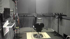
- No eating and drinking allowed in the lab. This includes drinking of water. Exception: during an EEG measurement drinking from water bottles that can be closed is allowed for subject and experimenter in the experimental room (see Figure 3), due to the long procedure of fitting the cap and the importance of keeping both subject and experimenter awake. Take care not to spill any water!
- Being in the lab before 7 and after 18 o’clock and on weekends is not preferred. The entrance to the lab (the big doors after the elevator) will be locked from 18 o’clock to 7 o’clock the next day! Make sure you always leave the lab before 18 o’clock! In case of entering before 7 o’clock and staying after 18 o’clock a Radboud card with access rights (with pin code - arrange via Judith) is necessary. When you are planning to be in the lab outside these times, especially for weekends, authorization of a senior researcher is required.
- Report to your senior researcher if supplies are missing and if anything is broken or doesn’t function. In the latter case also report this in the Issue tracking system at gitlab.science.ru.nl.
- Depending on the current COVID-19 regulations of the Radboud university, Donders center and the government, the following rules will apply. The distance between the experimenter and the subject will be at least 1.5 meter, except during the placement of the EEG cap, when the experimenter will wear a disposable mouth-mask, a clean lab coat, and gloves. The subject can also wear a mouth-mask and gloves (available in the lab), but that is not required. All equipment that needs to be touched by the subject will be cleaned and disinfected beforehand and between measurements. The airco must be on and before and after the measurements the doors will be kept open until you leave.
- Always keep record of your experiments in your lab journal.
Handling subjects
- Each experiment must be recorded in your lab journal (blue book),
- Each subject needs to sign the Consent form (located in the cabinet on the left side of the lab, to the left just out of the view shown in Figure 2) before start of the experiment.
- The questionnaire (also in above mentioned cabinet), must be completed for each subject and afterwards pasted into your lab journal.
%todo
Add: Ear checking/cleaning procedure
Add: always start with audiogram measurement.
Add: Cleaning procedure for this lab (it is now and then necessary to clean the floor etc…) + where to empty the bins.
Disposables
For the preparation of the subjects you need all types of disposables like alcohol, lotion, cotton pads, electrolyte gel, etc... You can find information about these items in NIRS-EEG lab disposables, and also info where to order them when needed.
Cleaning procedures
Washing of towels and lab coats is arranged in the COVID-19 procedures.
Procedure for data storage
Important: follow the RDM (Research Data Management) procedure of the Donders, see: https://www.ru.nl/donders/research/research-data-management/ Put your data (and only your data, no scripts) in directory: C:\DATA\<folder with your initials> or in the my documents directory of the PC you use for the measurement. Backup your data in the Donders repository (data.donders.ru.nl) or to one of the department network drives. You can use the network location: mbaudit3-srv.science.ru.nl for EEG data and mbaudit4-srv.science.ru.nl for fNIRS data. Of these network drives a backup is made regularly. On the lab PC: click the Start button, click “Computer” => Map network drive. Choose a drive letter and fill in for the Folder: “\\mbaudit6-srv.science.ru.nl\mbaudit6”. Check the options “Reconnect at logon” and “Connect using different credentials”. Use your science login to connect.
- These network drives are intended to back up your raw data. You may copy data to your own PC (or external drive), but you should never modify or delete the files on the network drives! For more info, see Research Data Management.
- Also save a backup of all scripts and other files that are important to repeat the experiment and your analysis on the network drive.
When you don’t need the data any more on the measurement PC and you entered the data in the Donders repository, you can remove the data from the measurement PC.
Lab reservation
Reserve lab time with QReserve. First ask for a new account or – in case of students – for the login of your supervisor. Click “Department of Biophysics” on the Dashboard page and choose Resources - NIRS-EEG Lab.
Location
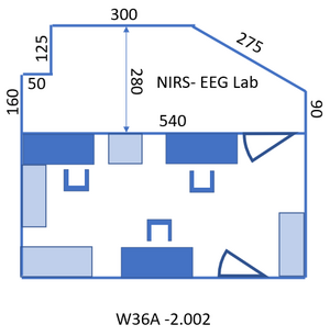
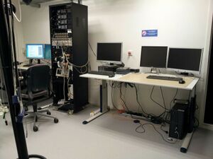
Access to the lab: take the last elevator at the opposite end of the building from wing 8 to floor -2 and follow the signs “Biophysics labs” to the room: A1 -2.002, the NIRS- EEG lab. Entry code of the room: ask your supervisor. To walk back to the elevator: follow the signs “Huygensgebouw”. Toilet: exit the lab to the right, turn left after the graffiti, the two doors to the right after the stairs and before the big door. Figure 1 gives the layout of the lab. The lab consists of two rooms, see Figure 2 and Figure 3. The first, where you enter the lab, will be referred to in this protocol as “control room” since the PC’s are located over there. The second will be called “measurement room”.
Setup of the main PC

The PC to the left in the control room is used to generate stimuli and control the experimental flow over the TDT (Trucker-Davis Technologies, USA, see next chapter).
- Press the on button of the PC (see Figure 4).
- Ask your supervisor to create an account on the PC you use or provide you with the login information of an existing account. In the latter case, you don’t have to perform the steps below, but read them so you know where to find the scripts and the information you need. Remark: references in this protocol to “your initials” or “your first name” indicate the name of this user account.
- Experimental and data analysis scripts can be found at: https://gitlab.science.ru.nl (more specifically: https://gitlab.science.ru.nl/marcw/biofysica/tree/master). Ask Marc van Wanrooij to give you access to biofysica and biophysics_labs. Here you can:
- Report / view Issues in https://gitlab.science.ru.nl/marcw/sphere_lab/issues. Label your issue with [EEG/NIRS]
- Download the most recent version of all software and put that in C:\gitlab\[Folder with your first name]\biofysica.
- To easily add all files in the biofysica directory to your Matlab path, add a file “startup.m” in the directory C:\users\<your user name>\My Documents\MATLAB with the line:
addpath(genpath('C:\gitlab\<Folder with your first name>\biofysica')); - Never change the files in C:\gitlab\<Folder with your first name>\biofysica, so you can easily update all files from gitlab. Updating ‘the git way’ instead of plain downloading requires a different approach, using git tools. This may not be needed by all users, but if you change programs or scripts frequently, using git tools is very convenient.
- Place your own scripts (Matlab and rcx files, see chapter: “Create stimuli and interact with the buttonbox”) in (a subdirectory of) C:\users\<your user name>\My Documents\MATLAB. Be sure to always use new names for your own scripts and functions to avoid mix-up with the files in the biofysica directory.
- See “$2.1 Lab procedures” above for data storage and backup procedures.
Overview of the Setup
Sound system
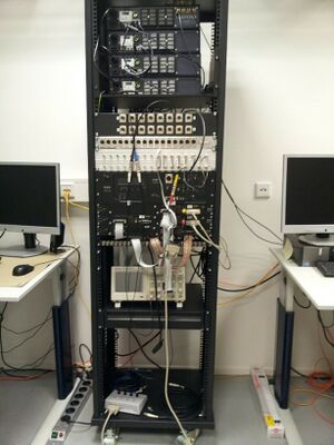
TDT equipment (see Figure 5) is used to generate sound stimuli and present them on speakers or a headphone in the measurement room. The RZ6 is central: it generates the stimuli and presents them to the PM2R multiplexers (labeled: “device 1”, “device 2”, and “device 3”), which send the stimuli to the correct speaker(s). Furthermore, the RZ6 registers the output of the button box (which button is pressed by the subject) and controls the input (which lights turn on) to the button box. It can do (limited) data acquisition and processing. The RZ6 also sends timing signals (“triggers”) to the EEG measurement equipment (the Refa; TMSi) in the measurement room. That is the only connection between the TDT and the EEG equipment.
Table 1 gives an overview of the coding to activate each of the 32 speakers. Negative angles represent the left hemi field (left of the center). Device and channel counting start with 0.
| Speaker position (degree) | Device | Channel | Speaker position (degree) | Device | Channel |
|---|---|---|---|---|---|
| 0 | 0 | 0 | |||
| -5 | 2 | 1 | 5 | 0 | 1 |
| -10 | 2 | 2 | 10 | 0 | 2 |
| -15 | 2 | 3 | 15 | 0 | 3 |
| -20 | 2 | 4 | 20 | 0 | 4 |
| -25 | 2 | 5 | 25 | 0 | 5 |
| -30 | 2 | 6 | 30 | 0 | 6 |
| -35 | 2 | 7 | 35 | 0 | 7 |
| -40 | 2 | 8 | 40 | 0 | 8 |
| -45 | 2 | 9 | 45 | 0 | 9 |
| -50 | 2 | 10 | 50 | 0 | 10 |
| -55 | 2 | 11 | 55 | 0 | 11 |
| -60 | 2 | 12 | 60 | 0 | 12 |
| -70 | 2 | 13 | 70 | 0 | 13 |
| -80 | 2 | 14 | 80 | 0 | 14 |
| -90 | 2 | 15 | 90 | 0 | 15 |
Table1: device (multiplexer number) and channel coding for each speaker.
EEG
The EEG system (Refa) has 72 channels. It is connected via an orange bi-directional optical fiber to the PC to the right of the TDT in the control room. The EEG data is measured and saved continuously during the experiment (so not per trial). In a separate channel (channel 73, named Digi) the trigger signals from the RZ6 are saved. Only the button response and the timing of the button press need to be saved via the RZ6 and the Matlab script (of course you are free to program a script that saves all kind of other information, for example regarding the exact timing of the stimuli).
NIRS
%todo
Present sound stimuli
RZ6

- Check if the connection of the cables is correct for your experiment.
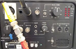
- Attention: always leave the attenuation knob (to the left in Figure 6) at 0.
- If the electrostatic speaker driver is not being used, make sure that the ON/OFF switch (to the right in Figure 6) is in the OFF position to reduce noise on the RZ6.
- To start the TDT: switch the four power buttons indicated in Figure 7.
- Do a test run with your Matlab script.
- When you want to hear the A or the B sound output directly from the small speaker integrated in the RZ6 (lower right corner in Figure 6), you can put the switch next to the speaker either to “A” or “B”. When you hear nothing turn the volume up with the knob (in the middle row) labeled “Mon level”.
- Connect the analog output signal (for example output OUT-A) to one of the inputs of the oscilloscope – see Figure 8 – to check the output signal.
- If everything is prepared do a test run with your subject before starting the real measurement.
- For performing EEG measurements see chapter 10. For NIRS measurements: see chapter 12.
Oscilloscope
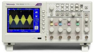
Figure 8: Oscilloscope
The oscilloscope is a Tektronix MSO 2024.
The large round button in the right lower corner changes the x-axis: the time per division (shown in white in the center below the x-axis). There are four input channels, marked 1 to 4 with different colors. You can change general channel settings by pressing the colored button of the channel. Each bigger knob below the number changes the y-axis of the channel: the voltage per division (shown in the color of the channel below the x-axis). Each smaller knob above changes the offset of the y-axis of that channel. The “Probe ..X Voltage”, listed in the display to the right, should be at 1X voltage. Manual: broken link.
Create Stimuli and Interact with the Button Box
All information regarding TDT system 3 equipment (see Figure 5) can be found in the directory TDT of the gitlab\<Folder with your first name>\biofysica directory that you created in paragraph 2.7. You can also find information in directory C:\TDT. Links for up-to-date manuals on the Internet:
When you want to change a circuit, the RPvdsEx manual is important. In the next chapter, the hardware setup is described. Ruurd Lof made a toolbox with standard functions that you can use, for info ask him or Günter Windau.
Examples of EEG measurement implementations, consisting of an RPvdsEx circuit file (extension: .rcx) that can be run out of Matlab, a Matlab file (.m) to run the application, and possibly files with the experimental settings (.mat), can be found in gitlab\<Folder with your first name>\biofysica\eeg. If there is a circuit file with a name ending on “_standalone”, you can load and run this in RPvdsEx (first turn on the TDT equipment), further see chapter 0 and play with the settings.
Always first turn on the TDT equipment (see Figure 7) and then run the Matlab file.
Sound hardware
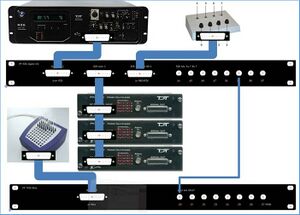
RZ6 sound processor
Info about the RZ6 can be found here: RZ6 info page.
Figure 9 shows the devices, patch panels, and connections on a photograph of a part of the TDT rack.
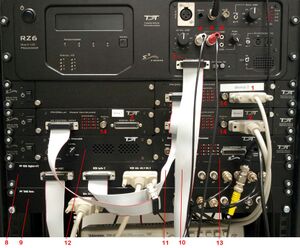
==Hardware depicted in figure 10==
1: PM2Relay multiplexer device 0
2: PM2Relay multiplexer device 1
3: PM2Relay multiplexer device 2
4: Analog out A of the RZ6
5: Analog out B of the RZ6
6: Analog out A and B combined for headphone
7: Digital I/O of the RZ6
8: Patch panel that redistributes the Digital I/O of the RZ6 (nr 7), labeled “Bytes A, B,C” to different connectors:
   -byte C, input for the multiplexers, to the connector labeled “RZ6 byte C”;
   -I/O for the response box via “RZ6 bits A0…3 B0…3”
   -output for triggers via the BNC’s A4…A7 (byte A bit 4-7) and B4…B7 (byte B bit 4-7).
9: Patch panel that sends the input to the BNC connectors D0…D7 to the Refa 8-bit trigger input (marked 3 in Figure 10).
10: Flatcable connecting the Digital I/O of the RZ6 to the RZ6 Digital-I/O patch panel (8).
11: Flatcables connecting the PM2Relay multiplexers
12: Monitor speaker (for example to connect a microphone from the lab)
13: Medusa (has been removed)
14: Analog input for the multiplexers (connect with 4 or 5)
The upper right corner of Figure 10 (see also Figure 6) shows the Input/Output interface of the RZ6, the right part of the RZ6. The upper row contains the input connectors, to the left for example you can connect a microphone. The frequency response of the analog inputs is DC-0.44*Fs if Gain=1. With amplification the inputs are AC coupled to prevent clipping. An external anti-aliasing filtering is not needed because sigma-delta ADCs are used. The middle row contains the analog output.
Please leave the left knob for manual attenuation (to the left in Figure 6) on 0. If you want to attenuate the output you can use the attenuation task in BIOX. Out-A and Out-B are the output of the A and B channels, the signals for the speakers. The voltage out is +/- 10 Volt (stay below the 10V to avoid clipping), see the “RZ6 Multi I/O Technical Specifications” part of the RZ6 spec. These signals are also passed to two stereo headphone outputs, the connector labeled “A&B” and “Mon”. An extension cord for a headphone is fed through the wall to the measurement room. Use the “Mon” output for monitoring only. The analog outputs are amplified and can deliver up to 12 Watt RMS into 4Ω loads. BNC and A&B jacks have separate power amplifiers.
BIOX
Programming of sound stimuli and button response measurements are done in Matlab. For this purpose you can use the BIOX toolbox, which is part of the biofysica toolbox.
Calibration
%todo: Protocols for Calibrations
- Calibration of speakers (sound levels + faithful reproduction of the frequencies / waveform). The sound level meter is used for measuring the output of the speakers. Measurement results are stored in the grey box in the cabinet to the left of the control room.
- Calibration of the sound level of an insert earphone, see: mbaudit6: Description_insert_ear_calibration_181115.docx
- Record the output of an insert earphone.
- Distance measurements
- Measurement of the angle between speaker and subject
- Check if the surface of the speaker is sufficiently perpendicular to the line from the center of the speaker to the head of the subject.
EEG equipment
%todo: describe EEG equipment
Manuals
- To do: checken
- SAGA manual and technical specification of the SAGA can be downloaded via: TMSI knowledge base
- Manuals for water and gel electrode caps %todo
- Manual for the TMSi Polybench software: open the patient data manager on the EEG PC, now you can access it through the question mark in the upper right corner. Further a description and reference can be found at http://www.appliedbiosignals.com/index.php?id=polybench. Polybench is a software application toolbox for the creation of customized applications that work with (all kind of) physiological signals. You can analyze and process signals, also real-time. Further you can design protocols and graphical user interfaces. The Quick Recording application with the Polybench configuration for the Refa can be downloaded from %todo.
- Matlab class to import Refa measurements into Matlab or to perform the measurement directly from Matlab without using the above mentioned Polybench software can be downloaded from TSMI Software.
The Refa

According the Refa manual (see Manuals) no high pass or low pass filters that can cause signal phase shifts or filter overflows are present in the Refa. The following filtering is applied in the Refa: a 1st order low pass filter before the analog-to-digital converter (ADC) with a -3db point at 6.8 kHz. Next to that, the ADC of the device has a digital sinc5 filter with a cutoff frequency of 0.2 * sample frequency. The Refa of TMSI is connected via two optical cables to the right PC in the lab. But the last meter is a USB cable (under the table). This is according TMSi not a problem, but check: broken link “Thou Shalt Not Allow Thy USB Cabling to Be Cast Loose Upon the Ground, Lest Thee Be Consumed By Fire”. Also standard USB cabling is not intended for use around magnetic fields. It would be better to use EEG equipment that runs on batteries.
Question: could there be problems caused by the long cables of the speakers, for example the picking up and amplifying of 50 Hz electrical noise? Answer: all electrical equipment and cables cause problems.
Use the Field Analyzer (NFA 400 of GigaHertz solutions, current location – Sep 2021 - in a black box in the cabinet to the right in the EEG lab) to check the magnetic and electric fields. Put the Data Recorder part of the SAGA close to the subject and seat the subject as far away from cables, sockets and all electrical devices as possible.
Advice of TMSi: use electrostatic discharge safe chairs for the subject (with head rest) + use a wooden or at least not-metal bench to put the Data Recorder on. Further use ESD mats everywhere on the floor in the measurement room, see: broken link
The Saga

The SAGA consists of a Docking Station (serial number: 1005200002) and a Data Recorder (sn: 1000200008). To do: add picture and check remarks below.
First install: always docked, then in the first screen of the QRA choose advanced options and then Fiber (Optical connection) => Switch button. If after connecting the fiber to docking and data the green fiber connection light on data is on: no need to dock the data part, but always in the first screen of the QRA choose advanced options and then Fiber (Optical connection) => Switch button.
The 1-bit trigger input (DIGI) of the SAGA can only handle 3.3 volt! The pulse height must be between 2.3V and 3V.
Name in the Signal Viewer: DR Trigger.
(X-axis and y-axis are the internal accelerator)
In the Poly5 the 1-bit trigger is in the STATUS signal: when this becomes 1024 (32 less - bit 5 from the right- than 1056, the default value) a trigger is detected.
Caps
The caps are manufactured by MFI. The caps have integrated passive electrodes. The electrodes are sintered Ag/AgCl electrodes. For electrode positions of the 64 electrodes Refa cap: see Figure 22. This is the 10-10 positioning with some alternations. See: https://www.acns.org/pdf/guidelines/Guideline-5.pdf . The electrode positions of the 64 electrodes SAGA caps is almost identical, only the placement of AF4, AF3 and the GND ground is a bit different. There are also 32 electrodes Refa caps (10-20 positioning with some alternations).
The caps are bought from TSMi, who currently uses Medi Factory as manufacturer. Only the white M cap uses the electrodes from TMSi and the cap from Easy cap. Refa caps can also be used for the SAGA, using the cable adapter.
%todo: add picture of cap.
-
Cap for Refa64, positioning and coding of the electrodes
-
Cap for Mobita32, positioning and coding of the electrodes
Performing EEG measurements
Every new student or new staff needs to be instructed by an experienced researcher before performing an EEG experiment!!
Informing the subject
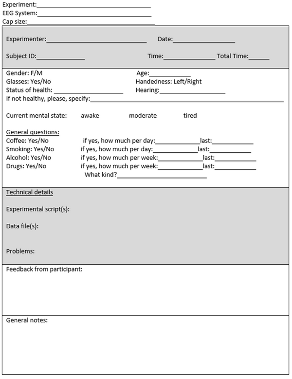
Tell your subject beforehand how long the experiment will take and sketch the procedure globally. Ask the subject to wash their hair the night before, to use no hair products except shampoo, to get enough sleep and to take a warm sweater – because the lab can be cold. Further inform the subject that no eating or drinking is allowed (except for some water, to be provided by you). After preparing the subject show the effect on the signal caused by eye blinking, swallowing, clamping the teeth and moving in general and instruct the person to sit as relaxed as possible. For an example of a complete checklist see the appendix.
Prepare as much as possible before the subject arrives. All needed supplies, caps, wristband and wires are in labeled boxes in the cabinet to the right when you enter the lab. Please put everything back in the correct place after your measurements (for the cap and wristband: only as soon as they are dry).
Measurement preparation
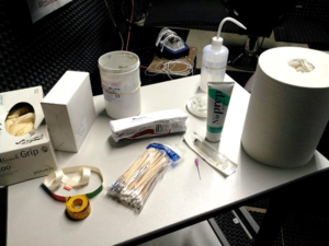
Needed for skin/head cleaning for EEG preparation (see Figure 23: EEG preparation)
- Disinfectant alcohol for cleaning of the forehead, the mastoid bones, below the eye, next to the eye where the electrodes to measure blinking will be connected. Use this also to clean the scalp (first check with the subject).
- Remark: when the subject used gel or other hair products except shampoo in the hair, the hair needs to be washed first.
- Gauze sponges for applying the alcohol.
- Latex gloves if needed
- Lots of paper + waste bin
- Remark: the use of NuPrep for scrubbing the skin is not recommended. It can be used locally on the exact location where an electrode will be placed, for example the eye electrodes or in case of working with separate electrodes for the mastoids. NuPrep has (low) conducting properties, which makes it unsuitable for overall use because of the risk of electric connections between electrodes.
Needed for making connection between electrodes and scalp
- New (blunt) needle
- Syringe (please don’t re-use so we are sure that we insert clean and fresh gel)
- Abralyt HiCl abrasive electrolyte gel. This contains 10% salt, has a better long term stability and reaches a stable impedance earlier than Abralyt 2000 electrolyte gel. Info of Robert Oostenveld about the electrode-skin interface:
- “In the body current is conducted by ions (Na+, K+, Cl-). In the wires current is conducted by electrons. The skin-electrode interface acts as a half-cell where ions combine with electrons (and vice versa, like in a battery) This causes a constant DC electrode potential of 200mV for AgCl electrodes and gel, more for other materials. Note that ERP effects (~ 1uV) are about ~200.000 times smaller. Impedance changes, sweating, movements, etc. cause small fluctuations in this 200 mV (which are large compared to the ERPs). The gel reduces impedance and stabilizes the half-cell electrode potential compared to dry electrodes.”
- AgCl sticker electrodes in case of working with separate electrodes for the mastoids. But first tests with this did not produce stable results and TMSi advises to use only one type of electrodes in a measurement, because of the DC offset, which is different for different electrodes and changes different for different type of electrodes.
- Further the green ground electrode, a black wrist band to connect it to the ground and the eye track electrodes are needed.
- %todo: description of the procedure (make picture) for the application of the EOG electrodes.
Fitting the cap
- A good fit of the cap is very important. Use the measurement tape with colors to select the right cap (yellow: small, red: medium, blue: large). The caps are color coded on the velcro that goes under the chin. Measure the circumference of the head and record it – and the following head measurements – in the lab journal.
- First clean the skin and hair/skull with disinfectant alcohol as described above. Nuprep can be used for scrubbing the skin on the mastoids.
- Fit the cap on the head with the cable at the back. Fit tight but check that it is not too tight.
- Measure the distance from the nasion (depressed area between the eyes) to the inion (the most prominent projection of the protuberance which is located at the posterior inferior - lower rear - part of the human skull, for most people you can feel it as a prominent bump). The distance from nasion to FZ should be 0.3 x this distance. Alternatively you can check the distance to Cz, this should be exactly half of the distance of the nasion to the inion.
- Measure the distance from the Tragus of the ear to the ear over the head and check if CZ is exactly in the middle.
Application of the gel
- Solid parts of the gel can possibly form a residue on the bottom of the gel pot, in that case gently stir the gel before inserting it in the syringe. The gel can only be used for 12 months after the first opening of the pot.
- Usually the electrodes at the back of the head need some more time to reach low impedance (the electrode-head distance can be a little larger at the back due to the hair and fitting of the cap), so start the filling of the electrodes at the back of the head.
- Use the blunt needle to gently push the hair away.
- Push the ring against the head, insert a tiny bit of gel and scrub with the blunt needle.
- Repeat this after scrubbing all contact places, now use more gel to fill the hole. Don’t forget to push each ring against the head during filling.
- Check the impedance after filling all electrodes. For each electrode that is not below 10kOhm repeat the scrubbing with the blunt needle and add a little gel if needed.
- Don’t use too much gel, it can form bridges between electrodes.
Connect to the Refa

- Make sure the Refa is switched off: the power switch on the backside of the Refa must be “off”, see Figure 20.
- Connect the Refa in the measurement room to the trigger cable, the 25-pins connector marked “REFA”.
- Connect the Refa to the orange optical cable. To disconnect it later on, push the small protruding part at one side of the connector and pull.
- Get the power connection for the Refa from the top shelf of the cabinet that is directly to the right when you enter the lab. You need a blue box (a 10 VDC rectifier, marked at the bottom: TMS, sup3) and a power cable to connect the Refa to the mains. The insertion of the cable is a bit tricky, notice the small notch at the upper side and turn the black part to the right, see Figure 24.
- Take care that the black cable to the 220V doesn’t touch the grey cable, this cable contains the subject ground which should be as far away as possible from 220V sources.
- Connect the electrode board adapter connector marked “1” to the upper part of the Refa and the connector marked “2” to the lower part (see the photo in Figure 21).
- Always switch off the Refa first before connecting plugs of the EBA to the system.
- Set the power switch on the backside of the Refa to “on”, see Figure 20. All orange lights next to the cables for each channel should light up shortly, the green light of the power should stay on.
- Wet the black wristband with lukewarm water. It has to fit tightly around the arm. Connect it to the green ground cable and connect the other side of the cable to the ground connector in the upper part of the Refa (see Figure 21). It is very important that there is a good contact between the patient ground electrode and the skin. The better the contact the better the quality of your measurement signal.
- Regularly feel if the wrist band is still wet, it can dry up in about half an hour and should be wetted again. Take care that the clip connector with the cable is dry.
Suggestion of Robert Oostenveld: when you connect the ground to the bone of the elbow you get less problems with muscle artefacts in the arm. According his experience a ground far from the other electrodes has the disadvantage of adding artefacts in the part of the body between electrodes and ground to the signal.
Lab disposables
All lab disposables needed for the EEG and NIRS measurements are described in NIRS-EEG lab disposables
%todo: procedure for ordering lab disposables
The measurement


Start the Quick Recording Application. Never start the Application twice! If you do you can get the odd-even warning in the impedance measurement (pink colored circles, usually this indicates that not yet an odd and an even electrode are filled with gel, this is necessary to get contact). In the Signal viewer the signal is 0. This is because the signal is not updated. Confusing is that the software gives no errors and indicates that the data connection via the optical fiber is OK. Don't forget to switch on the Data recorder! In case of problems shut off everything, also disconnect the power of the Docking station .
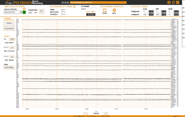
When the Refa is connected to the power the EEG measurement software, which is called “Polybench”, can be started. This software is installed on the PC on the desk to the right in the control room (see Figure 2). The left monitor is used for NIRS, both monitors to the right and the monitor in the measurement room (see Figure 25) are used for the EEG software. Use the small box with the four buttons (in between the monitor for NIRS and the monitors for EEG, see Figure 26) to switch between the NIRS screen and the three other screens. When the second button of the small box is pressed both monitors to the right and the monitor in the measurement room are active. When the screen stays black check the power button at the back to the right, the touch button below the front to the right, the connection to the power board and the switch on the power board on the ground. Log in to the PC with account: eeg, password: ask your supervisor. Start the TMSI Polybench software from the desktop icon. Use the Normal user: 0000 (Admin: 1234). Move the Polybench window to the right screen so you can still access the file manager and other programs via the main screen.
- If the Polybench main window still appears at the left screen: start as Admin (1234) and uncheck “Full-screen” in the “Applications” menu of the Data Manager to work in Windowed mode. Start the application again as normal user.
- Choose user 1, mmn
- Click to the right on “50kOhm impedance colour”, which has the color scale of the impedance running from 0 (dark blue) to 50kOhm (red). This application is only used to measure impedance while applying the gel.
- Select the device (USB 120140126) with the pull down menu in the top left corner.
- Click Start, you can now switch between impedances and signal. To measure the impedance correctly at least one odd and one even channel (above channel number 4) and the Patient Ground electrode must be connected. In Impedance mode each impedance LED on the Refa will light up orange if the impedance of that channel is below 20 kOhm (this is the default value(?), the threshold can be changed in the application software (how?)), otherwise they will blink (correct?). Important: the impedance for each channel should be as much equal as possible. Preferable all impedances should be < 5 kOhm (lights indicating the impedance dark blue), at least they should be < 10 kOhm.
- Make a screenshot of the impedances and save this (using Paint). You can also exit the application and start the “Refa impedance Mode Recorder_Fullscreen” to make a recording of the impedances.
- When you are ready with the impedances exit the application and start “EEG Recorder v1.26”. Do not select a device, the device will be started automatically. If it does so correctly the box next to “Select device” is green, otherwise it is red. You can switch between Signals and Impedances (take care that the color scheme of the impedances is not equal to that of the “50kOhm impedance colour” recorder, dark blue can still me above 10kOhm).
- Check the acquisition sample rate in the top left corner and change if needed.
- EEG recorder v1.26 sometimes when used at 2000Hz wrongly saves wrongly a sample rate of 4000Hz, check if the time needed to pass from left to right matches the time scale on the x-axis (see below). If not: change the sample rate to another value, for example 1000Hz, and change it back again to 2000Hz.
- At the bottom of the Polybench interface you can change the time scale. To the left (below “Ranges”) the upper limit of the voltage to display can be entered. At the top the signal can be high and low pass filtered. ExG indicates the 64 electrodes. High- and low-pass filtering can be set in the upper right corner. Enter a number and click on the “1” on the black switch next to the number to activate the setting. Comment: the user interface is counter intuitive: when a 1 is shown the filter is not active, a 0 indicates that the filter is active, this is because the number indicates the possible change in activation and not the status quo.
- All these settings do not influence the measurement, only the raw signal will be stored.
- Start a test run of your stimulus presentation via the TDT (from the other PC) and show your subject on the monitor in the measurement room what happens when she/he clamps the jaws, moves the head and blinks.
- If you don’t see any signal: switch the Highpass filter below “ExG” to on by clicking on the “1” on the black switch, see the upper right corner in Figure 28. You can also use the ZeroOffset, AutoOffset and AutoRange buttons to the left.
- Test how stable the signal is when the hand where the wrist band is connected to is moved.
- Ask the subject to close the eyes and relax and see if you can recognize alpha waves. This is the only brain activity that you can recognize visually in the EEG signals.
- Check by setting the filters in the upper right corner if some channels contain a lot of 50Hz. In that case try if it helps to put the Refa on the ground or if the subject puts her legs on a bench (no metal!).
- Check if the trigger signals are visible in the digi channel (bottom channel). The trigger times and values are also saved in the separate excel file.

- Click REC to start recording. Figure 27 shows the record button. Figure 28 shows an overview of the Polybench interface.
- Check if the recording time “REC TIME” in the in the black box (see Figure 27) is counting to be sure you record. *When you want to pause the recording press the REC button, press it again when you want to continue recording. For the older versions of the recording software: Don’t use the STOP button for pausing, when you start recording again it looks as if the recording functions, in orange it states “RECORDING STARTED”, but the “REC TIME” is not counting and recording does not function (in v1.26 it is not possible any more to click the STOP button when you are recording).
- The µV values per channel to the right of the screen are the last values measured for each channel.
- Start your stimulus presentation via the TDT (from the other PC).
- Check again if the “digi” channel displays the triggers. An EEG recording without triggers is useless.
- Check if the measurement folder is created (see below: “Analysis of the measurement”) correctly, it has the date and time in its name. The name of the measurement file is identical, its size should become larger during recording.
Polybench interface during recording
Attention points during measuring
- Switch off the screen (with the button at the back).
- Switch off the TL.
- Remove laptops, smartphones, watches and other electronic devices from the measurement room. Switch off any equipment that is not needed during the measurement. When a laptop is needed don’t use the power supply of the laptop.
- Don’t use the PCs for anything else during the experiments, so the full capacity of the processors can be used for presenting cq recording.
Cleaning up after the measurement
Disconnect the cap from the equipment (and the patient). The cap needs to be thoroughly cleaned, all rests of the electrolyte gel need to be removed, a soft toothbrush can be used for that. Wash with lukewarm water. You can use some shampoo. Disinfection of the cap is not possible because of integrated electrodes. Remark: it would be best to rinse with distilled water after cleaning. (Info of the lab coordinators of DCCN and DCC.)
Be careful to keep the connectors dry. Dry the cap with a towel and let it further dry on the head stand. When the cap is totally dry it should be stored in the correct plastic sleeve.
- Never use the hair dryer for drying a cap.
The “Waterpik” water flosser can be used for cleaning.
Towel washing is covered in the covid lab procedures. The blue towels are to be used in the EEG lab only.
When using new electrodes, or electrodes left dry for several weeks, provide initial stabilization by soaking the electrodes in a 1% saline solution for at least 30 minutes. Reagent-grade sodium chloride is available from EEG Info. Mix one packet of sodium chloride with one gallon of distilled water. ONLY USE DISTILLED WATER OR PURE SALINE SOLUTION. If sintered electrodes are dry for 3-7 days they should be reactivated.
Question: is this necessary? Answer: better let MFI, the cap manufacturer, do this if needed, but is expensive.
Analysis of the measurement
Measurements are stored in directory: Documents / study 1 data/measurements/111/default-yyyymmddThhmmss (the date and time). Save the whole directory when you backup your data. Double click on a file to view the data in Polybench.
%todo: info about artefact recognition/removal + example scripts for data import in Matlab, ERP and frequency analysis.
Important points concerning the Refa
Sample rate: better record at 2000Hz and resample offline when needed. Noise is lower this way (see report: “170929 Noise measurements Refa.docx” of E. Noordanus). The ExG inputs (the unipolar channels, indicated with number 4 in Figure 21) are configured as a reference amplifier: all channels are amplified against the average of all connected inputs. Average referencing makes it possible to re-reference in software to any montage you want. The BIP inputs (the bipolar channels, indicated with number 6 in Figure 21) are used to measure two physiological signals differentially to each other. With the average reference concept, you can choose an electrode afterwards to be the common reference. When an electrode gets loose from the body, the electrode goes in “overflow”. The electrode is then immediately thrown out of the reference calculation and you won’t see any effect on the signals. You need to exclude electrodes with a bad signal (for example because they got partly loose during the measurement) after the measurement, otherwise all signals are influenced by these electrodes. Manual exclusion of electrodes during the measurement is not possible (unless you just pull out the cable from the input on the front panel of the Refa before starting the measurement). You can read more about the reference calculation on the technology pages. The patient ground electrode (connected to the wrist band) is required, but it is not an active input. It is meant to keep patient potential and the amplifier potential at the same level, so that the amplifiers can function. The AFz/GND electrode can be used instead of the wrist band, for that the electrode must be filled with gel (which is not necessary when using the wrist band) and the tiny white wire marked “AFz/GND” must be connected to the patient ground input (indicated with 3 in Figure 21) of the Refa.
For isolation (protection against 50Hz mains interference and diminishing of movement artifacts) the Refa uses for each tiny electrode cable what is called by TMSI “True active signal shield”: the signal of the inner wire is put on the shield using the low impedance output of an amplifier. The shield has exactly the same potential as the signal wire in that case. There is no influence from the outside and there is no capacitance of the cable. It appears as if the cable is not there. The active shield technology can be used for bipolar, common reference and average reference measurements.
The input impedance of the active channels is very high (100 MOhm). The influence of electrode impedance is therefore very small. TMSi states in the Refa manual (chapter 5.1 Unipolar input channels) that no electrode impedance measurement is required. But this is disregards problems because of artefactually induced voltage differences between electrodes. In “Human Auditory Evoked Potentials” – Terence W. Picton 2011 chapter 2 is stated that an electrode impedance < 10kOhm is recommended, not only because of electromagnetic noise picked up in the electrode wires, but also because of artefactually induced voltage differences between electrodes. Active electrodes (equipped with preamplifiers) significantly decrease the amount of electromagnetic noise in the electrode wires that connect the electrodes to the amplifier. Since the Refa has active shielding it is not necessary to use active electrodes. But it remains important to reduce the electrode impedance and, most important, make the impedance of each electrode as much as possible equal to the impedance of other electrodes, in order to reduce the influence of electrode-scalp artifacts such as skin potentials. Discussed with Frodo Muijzer of TMSi: It is better to disconnect the cables of electrodes that have much higher Z than others. In theory you can get rid of the noise caused by noisy channels in the measurement of all channels by re-referencing, but that works based on linearity. Since the amplifier is complicated exactly because of non-linear effects it is questionable if the re-referencing really results in as good a measurement of an electrode as with a common reference.
Information about noise from Frodo Muijzer (former TMSi test engineer):
The amplifier has both white noise and 1/f noise. To protect the patient when electronics fail inside the amplifier, we have to place a 100 kOhm resistor in front of every input. Every resistor is a noise source (Johnson–Nyquist noise), which is constant for every frequency (White noise). The opamps that are placed directly after the input have a 1/f noise characteristic. Last the ADCs used are of the delta-sigma type (1bit), these have a noise that increases with increasing frequency. To limit this noise, a Sinc5 filter is applied inside the ADC, with the -3dB point at 0.2 * the sample rate. The total noise of the amplifier is a combination of the 3 elements above. At very low frequencies, the 1/f noise of the opamps is dominant (remark E.N: starts at 3Hz already, for some channels already at 10Hz, see report: “170929 Noise measurements Refa.docx” of E. Noordanus), for higher frequencies the white noise of the resistors is dominant, and at the highest frequencies the ADC noise is dominant (this is both an increase in noise due to the delta sigma effect, and a decrease in average amplitude due to the sinc filter.) The transition between the white noise and ADC noise happens around 0.1 * sample frequency. I do not know at which frequency the transition between the 1/f and white noise takes place. Since this is a very low frequency, the results are easily obscured by low frequency drift caused by temperature effects etc. I expect the corner frequency to be somewhere between 0.1 and 2 Hz, but I have no proof for this.
The NIRS equipment
%todo
Performing NIRS measurements
%todo: who will write this?
Appendix
%todo
Example of a checklist (ASSR-4DEEG experiment)
Before the experiment
- Tell the subject to wash his hair the night before (and not the morning of) the experiment and why
- Tell the subject to not use any hair products the morning of the experiment
- Tell the subject to sleep well the night before the experiment and why
- Explain to the subject what you will do before fitting the cap (alcohol, scrubbing, measuring)
- Explain to the subject how the cap is fitted and how the gel is applied
- Tell the subject that he could bring something easy to do with him while you are fitting the cap and apply the gel
- Tell the subject to bring a sweater and why
- Tell the subject how long the experiment is going to last
- Tell the subject what he can expect as stimuli and what his task is for these stimuli (focussing on the sound rather than explicitly left or right)
- Tell the subject that he could be tired for an hour after the experiment because of the concentrating
- Tell the subject that afterwards he can wash his hair, but it is also wise to take a shower the evening or morning after the experiment
During the experiment
- Make the subject fill in the consent form and the questionnaire
- Again, explain to the subject what you’re going to do in the next hours
- Make sure the subject is comfortable (for example joke a little)
- Tell the subject that if he finds something unpleasant or painful he has to say that. Respond adequately to this feedback; you should never do something on the subject he does not like.
- Prepare the head, fit the cap and apply gel according to protocol
- When preparing the head, fitting the cap and applying the gel, continuously tell the subject what you’re doing
- After placing the cap let the subject adjust it with 2 hands
- Lay a paper towel on the head rest to catch any gel escaping from the electrodes
- Make a screenshot of the impedances and save
- Let the subject hear the test sound and again tell him what the task is he should perform
- Turn of the power of the screen in the experiment room
- Turn of the TL lighting
- Start the recording and check whether a new file folder is made
- Check if the trigger signal is recorded (should be visible on the screen)
- Start the experiment
- Record the experiment and files in the lab journal
- From time to time check whether triggers are observed in the EEG signals and whether there are noisy channels or large alpha waves (sleepy) present
- Make screenshots of the EEG signals from time to time
- Between experimental blocks, check up on the subject. Offer him some water and ask him how it is going. Make notes of his answers and remarks in the lab journal.
- After the experiment, stop the recording
- Remove the cap, earplugs and ground electrode from the subject
- Remove most of the gel from the subjects hair using paper towels
- Let the subject wash his hair
- Thank the subject for his participation
- Clean everything according to protocol
- Save all files according to protocol
- Eventually let the subject know how his participation contributed to the study
