EM Field Head Tracking System specifications

Introduction
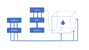
The EM Field Head Tracking System is used for recording head movements of the subject during a trial. The system consists of the following parts:
- Three oscillators at roughly 45, 55 and 65 kHz or 50, 60, 70 kHz for X, Y and Z direction.
- Three signal amplifiers that amplify the oscillator signals.
- six field coils that make a cube of roughly 3x3x3 meters.
- A small pick-up coil mounted on a glasses frame that is worn by the subject during the experiment.
- Three lock-in amplifiers that split the signal from the pick-up coil in the 3 frequency components and measures their envelope. They output analog signals between -10V and +10V.
- An acquisition device converts the analog output signals from the lock-in amplifiers to digital.
- A RZ6 multi I/O processor that records the acquired data.
- Software that converts the recorded data to head orientations using calibration data.
The following table contains the channel convention with respect of the three directions:
| Channel | Frequency | Orientation | Color | Polarity |
|---|---|---|---|---|
| Channel 1 | 45/50 kHz | Frontal | Red | Front = positive; Back = negative |
| Channel 2 | 55/60 kHz | Vertical | Blue | Right = positive; Left = negative |
| Channel 3 | 65/70 kHz | Horizontal | Yellow | Up = positive; Down = negative |
Parts
Lock-in amplifiers
Three Femto LIA-BV-150-H Lock-in amplifiers are used in order to separate the Frontal, Horizontal and Vertical signals from the pick-up coil. Each Lock-in amplifier has a Sinus Oscillator Module (SOM-1) that is used both as Field Modulation Signal and as Reference Signal. The Lock-in amplifier settings are set at the front of the device (see picture), except for the modulation/reference frequency which is set inside on the SOM-board.
The front panel of each LIA has four dipswitches:
- Mode: 1f means that the fundamental harmonic is measured (2f = second harmonic signal)
- Dyn.Res.: For dynamic reserve the settings Low (L) is preferred because the signal is normally large in comparison with the noise.
- PLL: For the Phase Lock Loop (PLL) the settings Slow (S) is preferred because the frequency is at a fix value. The phase is more stable in this setting.
- Ref.Thr.: Reference Threshold is set to 0V for analog signals (2V is for digital signals).
| Time constant Model „-H“ |
Hex switch 6dB/Octave |
Hex switch 12dB/Octave |
|---|---|---|
| 300µs | 0HEX | 8HEX |
| 1ms | 1HEX | 9HEX |
| 3ms | 2HEX | AHEX |
| 10ms | 3HEX | BHEX |
| 30ms | 4HEX | CHEX |
| 100ms | 5HEX | DHEX |
| 300ms | 6HEX | EHEX |
| 1s | 7HEX | FHEX |
Oscillators
Amplifiers
Resonance circuits
Wall coils
Pick-up coil
Lock-in amplifiers
ADC's
recording device
(RZ6 or RA16)