Auditory Perception Lab technical info
back to Auditory Perception Lab
Introduction
The Auditory Perception setup is a sound boot with about 30 speakers arranged in a quarter sphere. In the middle of the sphere is a chair where a person (the subject) can sit, so that his/her head is exactly in the center of the sphere. The subject can be presented with stimuli in the form of sounds or led flashes. The head movements of the subject can be tracked. The subject can also respond to stimuli by pressing a button. The experiments are controlled by a computer and electronics from outside the boot.
Booth
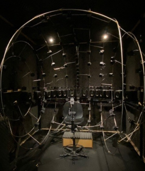
- Dimensions: LxWxH = 250x230x280cm
Description
The sound booth is an acoustically isolated room with sound absorbing materials on all walls and the floor to reduce reverberation. A 2.4 m diameter quarter sphere build of a metal structure holds about 30 small passive speakers. The speakers also contain two color LED's. In the center of the booth there is a chair for a subject. The chair is placed in a way that the head of the subject is right in center of the sphere. Large coils are embedded in the walls of the sound booth. The coils make a cube of about 2.5 m x 2.3 m x 2.8 m. These coils are used for head movement detection.
An infrared camera is installed in the booth. The experimenter has a monitor from which he/she can see the inside of the booth. The camera looks down on the back of the subject.
Acoustics
The Booth is acoustically isolated from its environment. The walls and corners are covered by acoustic panels. A double steel door isolates the booth from the operating room.
- Walls: Cinema Round Acoustic Panels
- Corners: Super Bass 90 Acoustic Panels.
- Floor: anti-fatigue rubber floor mat with holes
Computer
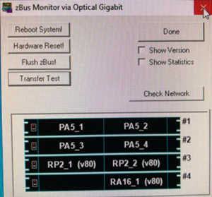
A windows computer with MATLAB, RPvdsEx and zBUSmon. The computer has an optical interface card (PO5e) for communication with the Tucker Davis equipment via the Optibit optical bus (FO5) at the back of the rack. The working of the optical bus can be monitored by the program zBUSmon program from TDT. This program has also some control functions for the optical bus. It shows all the connected zBus chassis and the TDT devices that are installed in each chassis. It also shows the version number of the installed firmware on the devices.
Software
The software consist of several parts:
- Matlab software for generating experiment files.
- Matlab software that runs the experiments.
- BIOX (RPvdsX) software for the RZ6 soundprocessor.
GenExp
The software that generates a experiment file is called 'genexp_xxxxx'. In the \biofysica\experiment\exp directory there are five examples:
- genexp_defaultcal.m
- genexp_defaultloc.m
- genexp_fartloc.m
- genexp_glausndloc.m
- genexp_student.m
Sphere Minor
The software mostly used is called 'SphereMinor'. It is a reworked copy of the 'SpherePrime' program of the Sphere Setup. It can be found in the \biofysica\experiment\sphereMinor directory. It has a graphical user interface (GUI) and is, except for the GUI, written in the procedural programming paradigm. Several functions have a parameter 'handles' as input parameter and as output parameter. 'handles' is a struct that contains nearly all information that is moved around in the program. Every function has the ability to change 'handles'. This way it acts as a global data structure.
A newer version (under construction) of 'SpherePrime' is 'BIOXPrime'. This program has a GUI build in the app designer of Matlab. The program is mostly written in the Object Oriented Programming (OOP) paradigm. The core of the program is a state machine. Due to its structure the GUI stays always responsive.
RPvdsX software
In the \biofysica\experiment\biox_rz6 directory there are .
When a RZ6 is used instead of a RA16 there is:
- sphere_RZ6.rcx
Electronics rack
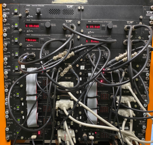
The upper half of the electronics rack contains 10 TDT Zbus devices chassis, each containing two TDT series 3 devices. The lower half contains the Field coil amplifier and the Femto LockinAmplifier as part of the head tracking electronics.
The following table shows all the zBus chassis from top to bottom, with the installed devices.
| Chassis | Front left | Front right | Back |
|---|---|---|---|
| Zbus | MS2 Monitor speaker | <empty> | |
| Zbus | PA5 Attenuator | PA5 Attenuator | F05 optibit bus #1 |
| Zbus | PA5 Attenuator | PA5 Attenuator | F05 optibit bus #2 |
| Zbus | SA1 Speaker amplifier | SA1 Speaker amplifier | |
| Zbus | RP2.1 Sound processor | RP2.1 Sound processor | F05 optibit bus #3 |
| Zbus | PM2R Multiplexer | PM2R Multiplexer | |
| Zbus | PM2R Multiplexer | PM2R Multiplexer | |
| Zbus | PM2R Multiplexer | PM2R Multiplexer | |
| Zbus | PM2R Multiplexer | PM2R Multiplexer | |
| Zbus | RA8GA2 multi DAC | RA16ba base station | F05 optibit bus #4 |
The next list shows all other electronics in the lower half of the rack from top to bottom.
- PP16 Patch panel for Medusa Base Station (2x)
- Digital event recorder
- Junction box panel (connects to junction box in sound boot)
- Trigger distribution panel
- Femto Lockin amplifiers
- Tektronics Oscilloscope
- Field coil amplifier
- Rack main power switch
- Patch panel for XLR output to Tannoy speakers
Optical Interface
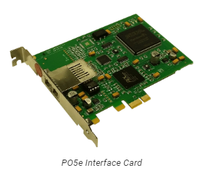
Four of the Zbus chassis in the rack have an optical interface (F05) at the back. These optical interfaces are connected in a loop with the P05e interface at the back of the computer. PO5e optibit bus F05 optibit bus (4x) Transfer rate: read 1.5 Mbit/s, write 1.0 Mbit/s N.B. The optical bus is not 100% stable. Once in a while it hangs up the program. Issue #196 on GitLab.
Sound system
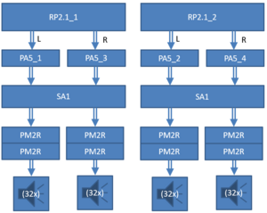
The sound system consists of two programmable DSP’s (TDT RP2.1’s) with each two DAC’s. An RP2.1 generates a sound signal that travels via a programmable attenuator (TDT PA5), a stereo amplifier (TDT SA1) and a multiplexer (TDT PM2R) to a patch panel inside the PLC cabinet in the boot and from there to a speaker. The multiplexing system consists of two sets of four multiplexers (TDT PM2relay). Each multiplexer has 16 channels. Only one channels per multiplexer can be opened at a time. The total number of channels is 128. Each RP2.1 controls four multiplexers. Since each RP2.1 has 2 DAC outputs, each output is connected to two multiplexers. It is therefore possible to play up to 4 different sounds at once over different speaker. Parts
- TDT RP2.1 (2x)
- TDT PA5 (4x)
- TDT SA1 (2x)
- TDT PM2relay Multiplexers (8x)
- Flat cables from RP2.1 to PM2relays (2x)
- Dsub25 cables from PM2relays to PLC cabinet in the boot (8x)
- Patch panel inside the PLC cabinet
- Speakers (116x)
Minx Min12 speaker system
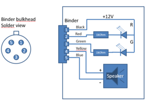
On the sphere frame Cambridge Audio Minx Min12 speakers are used.
Speaker specifications:
- Sensitivity: 86 dB SPL (@2.83 Vrms input)
- Frequency response: 150 Hz-20 kHz
- Impedance: 8 Ohms
- H x W x D: 78 x 78 x 85 mm
- Weight: 0.43 kg
The speakers are connected via 5 lead wires with a 5 pole binder connector at each end. Two leads are used for the speakers, three leads are used for the LED’s.
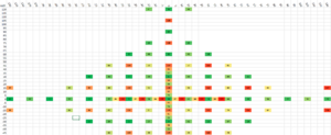
- RP2.1_1 Left : 26 speakers #000..#025
- RP2.1_1 Right: 28 speakers #032..#057
- RP2.1_2 Left : 32 speakers #064..#095
- RP2.1_2 Right: 26 speakers #096..#123
Total of 112 speakers
The speakers indexes that are not used are: [26 27 28 29 30 31 58 59 60 61 62 63 124 125 126 127]
Azimuths and elevations were measured by Sebastian Ausili in June 2015 and are tabulated in 'Sphere Measurement.xlsx'.
Tannoy speaker system

There are 14 Tannoy Reveal 402 speakers in the horizontal plane, positioned on small plateaus. These are active speakers with their own amplifier. The speakers are used when lower frequencies (50Hz-150Hz) are important. Due to hiss problems, the original block transformers have been replaced by toroidal transformers. The Tannoy speakers are connected with XLR cables to a special patch panel at the bottom of the electronics rack, and inside the boot to a panel on a XLR cable reel. Since the output of the TDT soundsystem does not have a balanced output, the shield of the XLR cables are connected to the minus leads. The Tannoy speakers can be connected to a multiplexer using a special flat cable that connects to the back of the XLR patch panel.
A flat cable with DSub25 connector from the back of the XLR patch panel you can connect the Tannoy speakers to a multiplexer. In the following table you see the mapping from the mux channels to the XLR channels. The collumn "Pin MUX" shows the corresponding DSub25 pin numbers.
| Channel | Pin MUX | XLR |
|---|---|---|
| X | 1 | GND |
| A0 | 15 | 1 |
| A1 | 3 | 2 |
| A2 | 16 | 3 |
| A3 | 4 | 4 |
| A4 | 17 | 5 |
| A5 | 5 | 6 |
| A6 | 18 | 7 |
| A7 | 6 | 8 |
| A8 | 19 | 9 |
| A9 | 7 | 10 |
| A10 | 20 | 11 |
| A11 | 8 | 12 |
| A12 | 21 | 13 |
| A13 | 9 | 14 |
| X | X | 15 |
| X | X | 16 |
The wiring of the XLR sockets on the patch panel is as follows:
- XLR-1: Shield = zwart
- XLR-2: Hot = rood
- XLR-3: Cold = connected to XLR-1
Speaker specifications:
- Active speaker: Bi-Amp (25W + 25W)
- 4" Woofer; 3/4" Tweeter
- Frequency range: 56 Hz tot 43 kHz
- Cross over freq.: 2.8 kHz
- Distortion: <0.9%
- Maximum sound pressure 101 dB
- Bass reflex system
- H x W x D: 240 x 147 x 212 mm
- Weight: 5.2 kg
LED system
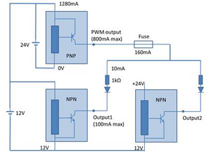
The LED system consists of a cabinet inside the sound boot with a Panasonic FP2 series PLC system (programmable logic controller). The PLC can independently switch 256 channels. The channels connect to a two color LEDs (red and green) that are mounted on the speaker. The PLC cabinet has two test buttons that can light all LEDs at once. The PLC system consists of a PLC with several IO units and is can be programmed by via a special USB cable.
Parts
- Trigger from Medusa base station
- PLC cabinet (houses PLC system)
- FP2 PLC system from Panasonic
- Break-out panel with 5 pole Binder connectors (128x)
- Binder cables (120x)
- LED mounting frames (120x)
- Red/Green LED’s (120x)
- Trigger converter (5V → 24V) for input trigger
- Trigger converter (24V → 5V) for trigger echo
Specifications Panasonic FP2 series
- FP2C2LJ FP2SH PLC
- 1 ms cycle time when <20.000 steps per cycle (120.000 steps max)
- Measured cycle time 1.35 ms
- FP2Y64TJ output unit (4x)
- 64 channels
- 24V NPN output
- Current 0.3A max
- Response time <0.3 ms
- FP2PXYPJ multi I/O unit
- PNP transistor
- PWM output 30 kHz
- Duty cycle 0-100% in steps of 1%
- Max output 800 mA
- FP2X16D2J input unit
- 16 channels
- Current 8 mA @24V
- Response time <0.2 ms
Specifications Red/Green LEDs
- Bivar 5BC-3-CA-F (Common Anode)
- Red 625nm (FWHM = 25 nm)
- Green 568 nm (FWHM = 30 nm)
- Nominal current 20 mA
- Voltage drop 2.1V
- 45 degree viewing angle
- Series resistor 1kOhm
- Actual current 10 mA @100% PWM
Trigger/Timing system


Description
The task of the trigger/timing system is to distribute trigger signals and record the timing of the triggers. In the standard situation when an experiment starts, the subject has to push a button to start a trial. The button push is registered by an arduino trigger bridge that outputs a trigger to the Medusa Base Station. The Medusa sends triggers to the RP2.1’s, the LED PLC and to the Event Recorder. The Event Recorder timestamps all the triggers and can be read out via ethernet. The arduino trigger bridge has a green LED that indicates that a trigger signal is generated and it has a test button that generates a trigger signal when pushed.
Parts
- Pushbutton (with 9V battery for 5V output)
- Arduino Trigger distributor (5V inputs (3x), 5V outputs (6x), 3V outputs (2x), testbutton)
- PP16 patch panel for analogue inputs
- PP16 patch panel for digital outputs
- Medusa Base Station (TDT RA16)
- Digital event recorder
Specification
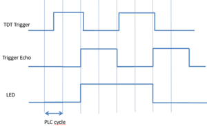
The LED PLC in the LED controller cabinet can be programmed by Matlab. The PLC stores a list of LED configurations. One configuration tells the PLC which LEDs should be on or off. In the standard mode (X = 0) the current configuration is changed to the next configuration by an electrical trigger signal from the Medusa Base Station. A stimulus of a single LED consists of two configurations, one with only that LED on, followed by one with all the LEDs off. The timing and the length of the stimulus are controlled by trigger signals sent from the Medusa Base Station. The PLC cycle of 1.35 ms is the limiting factor for the shortness of a LED stimulus. In practice the pulselength can be as short as two or three PLC cycles (2.7 ms or 4.0 ms) in the standard modus (X=0). The number of cycles the stimulus lasts can vary by one cycle. In practice there is always 1.35 ms jitter on top of a 1.35 ms delay for the start (and end) of a LED stimulus (see figure). When more precise knowledge is needed over the timing or length of the stimulus, a timing signal (trigger echo) sent from the PLC can be recorded. The trigger echo signal is lined up with the rising or falling flanks of the LED and can measure the real stimulus with an accuracy down to 40 µs.
When using short stimuli the X parameter can be used to control the exact number of cycles. When X = n the length of the LED stimulus is exactly n PLC cycles.
Head Tracking System
The Head Tracking System is used for recording head movements of the subject during a trial. The system consists of the following parts:
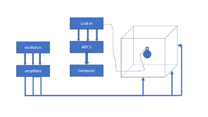
- Three oscillators at roughly 50, 60 and 70 kHz for X, Y and Z direction.
- Three signal amplifiers that amplify the oscillator signals.
- six field coils that make a cube of roughly 3x3x3 meters.
- A small pick-up coil mounted on a glasses frame that is worn by the subject during the experiment.
- Three lock-in amplifiers that split the signal from the pick-up coil in the 3 frequency components and measures their envelope.
- An acquisition device that converts the output signals from the lock-in amplifiers.
- A RZ6 multi I/O processor that records the acquired data.
- Software that converts the recorded data to head orientations using calibration data.