Buttonbox for RZ6: Difference between revisions
Jump to navigation
Jump to search
| Line 1: | Line 1: | ||
[[File:Tucker_Davis_RBOXRZ6.png|thumb|Response button box]] | [[File:Tucker_Davis_RBOXRZ6.png|thumb|Response button box]] | ||
==description== | ==description== | ||
The TDT RBOXRZ6 is a response button box for subjects in experiments with the RZ6. The box has four buttons and four leds. The box is interfaced with a D-sub25 connector that can connect directly to the Digital I/O input of the RZ6, or to the RBOXRZ6 input of the | The TDT RBOXRZ6 is a response button box for subjects in experiments with the RZ6. The box has four buttons and four leds. The box is interfaced with a D-sub25 connector that can connect directly to the Digital I/O input of the RZ6, or to the RBOXRZ6 input of the PP RZ6 Digital-I/O patch panel. | ||
*The buttons from left to right are connected to inputs A0..A3 of the RZ6. | *The buttons from left to right are connected to inputs A0..A3 of the RZ6. | ||
*The leds from left to rigth are connected to outputs B0..B3 of the RZ6. | *The leds from left to rigth are connected to outputs B0..B3 of the RZ6. | ||
Latest revision as of 13:05, 30 November 2023

description
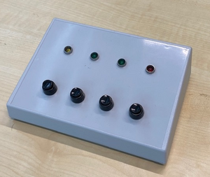
The TDT RBOXRZ6 is a response button box for subjects in experiments with the RZ6. The box has four buttons and four leds. The box is interfaced with a D-sub25 connector that can connect directly to the Digital I/O input of the RZ6, or to the RBOXRZ6 input of the PP RZ6 Digital-I/O patch panel.
- The buttons from left to right are connected to inputs A0..A3 of the RZ6.
- The leds from left to rigth are connected to outputs B0..B3 of the RZ6.