Sphere lab technical info: Difference between revisions
| Line 142: | Line 142: | ||
**Current 8 mA @24V | **Current 8 mA @24V | ||
**Response time <0.2 ms | **Response time <0.2 ms | ||
*LED’s | *LED’s | ||
**Bivar 5BC-3-CA-F (Common Anode) | **Bivar 5BC-3-CA-F (Common Anode) | ||
Revision as of 10:18, 19 June 2023
Sound booth
<todo>
Computer
<todo>
Electronics rack
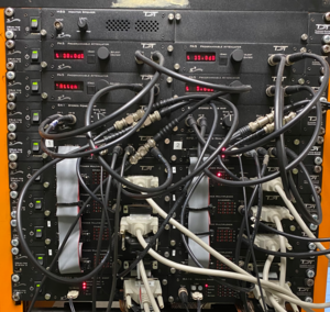
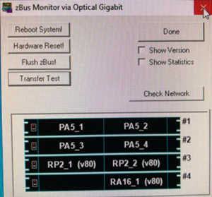
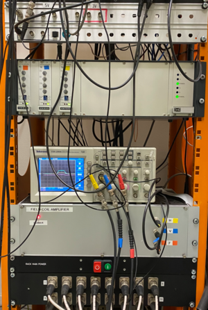
The upper half of the electronics rack contains 10 TDT Zbus devices chassis, each containing two TDT series 3 devices. The lower half contains the Field coil amplifier and the Femto LockinAmplifier as part of the head tracking electronics.
The zBus Monitor program has control functions for the optical bus. It shows all the connected zBus chassis and the TDT devices that are installed in each chassis. It also shows the version number of the installed firmware on the devices.
The following table shows all the zBus chassis from top to bottom, with the installed devices.
| Chassis | Front left | Front right | Back |
|---|---|---|---|
| Zbus | MS2 Monitor speaker | <empty> | |
| Zbus | PA5 Attenuator | PA5 Attenuator | F05 optibit bus #1 |
| Zbus | PA5 Attenuator | PA5 Attenuator | F05 optibit bus #2 |
| Zbus | SA1 Speaker amplifier | SA1 Speaker amplifier | |
| Zbus | RP2.1 Sound processor | RP2.1 Sound processor | F05 optibit bus #3 |
| Zbus | PM2R Multiplexer | PM2R Multiplexer | |
| Zbus | PM2R Multiplexer | PM2R Multiplexer | |
| Zbus | PM2R Multiplexer | PM2R Multiplexer | |
| Zbus | PM2R Multiplexer | PM2R Multiplexer | |
| Zbus | RA16ba base station | RA8GA2 multi DAC | F05 optibit bus #4 |
The next list shows all other electronics in the lower half of the rack from top to bottom.
- PP16 Patch panel for Medusa Base Station (2x)
- Digital event recorder
- Junction box panel (connects to junction box in sound boot)
- Trigger distribution panel
- Femto Lockin amplifiers
- Tektronics Oscilloscope
- Field coil amplifier
- Rack main power switch
- Patch panel for XLR output to Tannoy speakers
Sound system
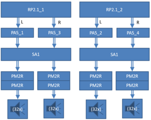
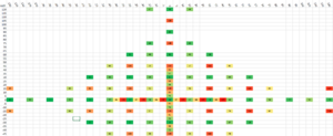
The sound system consists of two programmable DSP’s (TDT RP2.1’s) with each two DAC’s. An RP2.1 generates a sound signal that travels via a programmable attenuator (TDT PA5), a stereo amplifier (TDT SA1) and a multiplexer (TDT PM2R) to a patch panel inside the PLC cabinet in the boot and from there to a speaker. The multiplexing system consists of two sets of four multiplexers (TDT PM2relay). Each multiplexer has 16 channels. Only one channels per multiplexer can be opened at a time. The total number of channels is 128. Each RP2.1 controls four multiplexers. Since each RP2.1 has 2 DAC outputs, each output is connected to two multiplexers. It is therefore possible to play up to 4 different sounds at once over different speaker. Parts
- TDT RP2.1 (2x)
- TDT PA5 (4x)
- TDT SA1 (2x)
- TDT PM2relay Multiplexers (8x)
- Flat cables from RP2.1 to PM2relays (2x)
- Dsub25 cables from PM2relays to PLC cabinet in the boot (8x)
- Patch panel inside the PLC cabinet
- Speakers (116x)
Minx12 speaker system
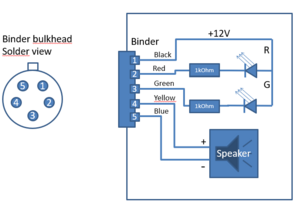
The Minx12 speakers are connected via 5 lead wires with a 5 pole binder connector at each end. Two leads are used for the speakers, three leads are used for the LED’s.
Tannoy speaker system

LED system
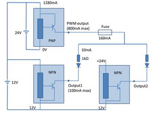
The LED system consists of a cabinet inside the sound boot with a PLC system (programmable logic controller). The PLC can independently switch 256 channels. The channels connect to a two color LEDs (red and green) that are mounted on the speaker. The PLC cabinet has two test buttons that can light all LEDs at once. The PLC system (Panasonic FP2) consists of a PLC with several IO units and is can be programmed by via a special USB cable.
Parts
- Trigger from Medusa base station
- PLC cabinet (houses PLC system)
- FP2 PLC system from Panasonic
- Break-out panel with 5 pole Binder connectors (128x)
- Binder cables (120x)
- LED mounting frames (120x)
- Red/Green LED’s (120x)
- Trigger converters (24V → 5V and 5V → 24V)
Specifications
The Panasonic PLC system is build of several units on a rail. They are all part of the FP2 series.
- FP2C2LJ FP2SH PLC
- 1 ms cycle time when <20.000 steps per cycle (120.000 steps max)
- Measured cycle time 1.35 ms
- FP2Y64TJ output unit (4x)
- 64 channels
- 24V NPN output
- Current 0.3A max
- Response time <0.3 ms
- FP2PXYPJ multi I/O unit
- PNP transistor
- PWM output 30 kHz
- Duty cycle 0-100% in steps of 1%
- Max output 800 mA
- FP2X16D2J input unit
- 16 channels
- Current 8 mA @24V
- Response time <0.2 ms
- LED’s
- Bivar 5BC-3-CA-F (Common Anode)
- Red 625nm (FWHM = 25 nm)
- Green 568 nm (FWHM = 30 nm)
- Nominal current 20 mA
- Voltage drop 2.1V
- 45 degree viewing angle
- Series resistor 1kOhm
- Actual current 10 mA @100% PWM