EM Field Head Tracking System specifications: Difference between revisions
Jump to navigation
Jump to search
No edit summary |
|||
| Line 20: | Line 20: | ||
|- | |- | ||
| Channel 1 | | Channel 1 | ||
| 45 kHz | | 45/50 kHz | ||
| Frontal | | Frontal | ||
| Red | | Red | ||
| Line 26: | Line 26: | ||
|- | |- | ||
| Channel 2 | | Channel 2 | ||
| 55 kHz | | 55/60 kHz | ||
| Vertical | | Vertical | ||
| Blue | | Blue | ||
| Line 32: | Line 32: | ||
|- | |- | ||
| Channel 3 | | Channel 3 | ||
| 65 kHz | | 65/70 kHz | ||
| Horizontal | | Horizontal | ||
| Yellow | | Yellow | ||
Revision as of 13:02, 29 November 2023

Introduction
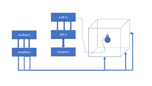
The EM Field Head Tracking System is used for recording head movements of the subject during a trial. The system consists of the following parts:
- Three oscillators at roughly 45, 55 and 65 kHz or 50, 60, 70 kHz for X, Y and Z direction.
- Three signal amplifiers that amplify the oscillator signals.
- six field coils that make a cube of roughly 3x3x3 meters.
- A small pick-up coil mounted on a glasses frame that is worn by the subject during the experiment.
- Three lock-in amplifiers that split the signal from the pick-up coil in the 3 frequency components and measures their envelope. They output analog signals between -10V and +10V.
- An acquisition device converts the analog output signals from the lock-in amplifiers to digital.
- A RZ6 multi I/O processor that records the acquired data.
- Software that converts the recorded data to head orientations using calibration data.
The following table contains the channel convention with respect of the three directions:
| Channel | Frequency | Orientation | Color | Polarity |
|---|---|---|---|---|
| Channel 1 | 45/50 kHz | Frontal | Red | Front = positive; Back = negative |
| Channel 2 | 55/60 kHz | Vertical | Blue | Right = positive; Left = negative |
| Channel 3 | 65/70 kHz | Horizontal | Yellow | Up = positive; Down = negative |
Parts
Lock-in amplifiers

%todo
Oscillators
Amplifiers
Resonance circuits
Wall coils
Pick-up coil
Lock-in amplifiers
ADC's
recording device
(RZ6 or RA16)