EM Field Head Tracking System specifications: Difference between revisions
| (20 intermediate revisions by the same user not shown) | |||
| Line 119: | Line 119: | ||
===Wall coils=== | ===Wall coils=== | ||
The wall coils make up a cube of about 3 x 3 x 3 m around the subject and create low frequency magnetic fields in three orthogonal directions (Frontal, Horizontal, Vertical). The opposite wall coils are paired into one loop that create one field together. | |||
Auditory Sphere Lab: | |||
*two winding's per coil. | |||
*resonator circuit. | |||
*3 m x 3 m coils | |||
Auditory Motion Lab: | |||
*two winding's per coil. | |||
*resonator circuit. | |||
*3 m x 3 m coils | |||
Auditory Perception Lab: | |||
*five winding's per coil | |||
*no resonator circuit. | |||
*2.3 m x 2.8 (2.3) m coils | |||
===Pick-up coil=== | ===Pick-up coil=== | ||
There are several head mounted pick-up coils. For the Auditory Sphere Lab and the Auditory Motion Lab the coils have a flux area of 152 cm2. For the Auditory Perception Lab the flux area is 298 cm2. | |||
* [[Head coil glasses Auditory Sphere Lab]] | * [[Head coil glasses Auditory Sphere Lab]] | ||
* [[Head coil glasses Auditory Motion Lab]] | * [[Head coil glasses Auditory Motion Lab]] | ||
| Line 129: | Line 145: | ||
===ADC's=== | ===ADC's=== | ||
The signal coming from the output of each Lock-in amplifiers is fed into an ADC. | The signal coming from the output of each Lock-in amplifiers is fed into an ADC. The ADC device is optically linked to the recording device (RA16 or RZ6). The range of the ADC's is -10 V to +10 V | ||
<pre> | <pre> | ||
Sphere | Auditory Sphere Lab : RA16 with RA8GA channels 1, 2 and 3 (system 3 version) | ||
Auditory Perception Lab : RZ6 with RA8GA channels 1, 2 and 3 (earlier version) | |||
Auditory Motion lab : RZ6 with RA8GA channels 1, 2 and 3 (system 3 version) | |||
</pre> | </pre> | ||
=== | ===Recording device=== | ||
(RZ6 | The recording of the output of the ADC's is done by either a RA16 Madusa Base Station or a RZ6 Multi I/O processor. The ADC devices are optically linked to the recording device. | ||
<pre> | |||
Auditory sphere lab : RA16 on 6103.5 Hz | |||
Auditory perception lab : RZ6 on 48828.25 Hz (divide by 10 ??) | |||
Auditory motion lab : RZ6 on 48828.25 Hz (divide by 10 ??) | |||
</pre> | |||
The raw data is saved. For display a 150 Hz low pass filter is used. | |||
Latest revision as of 13:39, 21 March 2024

Introduction
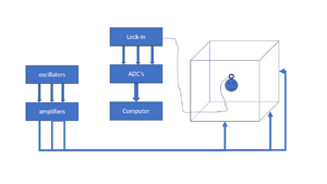
The EM Field Head Tracking System is used for recording head movements of the subject during a trial. The system consists of the following parts:
- Three oscillators at roughly 45, 55 and 65 kHz or 50, 60, 70 kHz for X, Y and Z direction.
- Three signal amplifiers that amplify the oscillator signals.
- six field coils that make a cube of roughly 3x3x3 meters.
- A small pick-up coil mounted on a glasses frame that is worn by the subject during the experiment.
- Three lock-in amplifiers that split the signal from the pick-up coil in the 3 frequency components and measures their envelope. They output analog signals between -10V and +10V.
- An acquisition device converts the analog output signals from the lock-in amplifiers to digital.
- A RZ6 multi I/O processor that records the acquired data.
- Software that converts the recorded data to head orientations using calibration data.
The following table contains the channel convention with respect of the three directions:
| Channel | Frequency | Orientation | Color | Polarity |
|---|---|---|---|---|
| Channel 1 | 45/50 kHz | Frontal | Red | Front = positive; Back = negative |
| Channel 2 | 55/60 kHz | Vertical | Blue | Right = positive; Left = negative |
| Channel 3 | 65/70 kHz | Horizontal | Yellow | Up = positive; Down = negative |
Parts
Lock-in amplifiers
Three Femto LIA-BV-150-H Lock-in amplifiers are used in order to separate the Frontal, Horizontal and Vertical signals from the signal that is coming from the pick-up coil. Each Lock-in amplifier has a Sinus Oscillator Module (SOM-1) that is used both as Field Modulation Signal and as Reference Signal. The Lock-in amplifier settings are set at the front of the device (see picture), except for the modulation/reference frequency which is set inside on the SOM-board.
| Kenmerk | LIA-BV-150-H |
|---|---|
| Model | Single Phase |
| Werkfrequentie | 50 Hz - 120 kHz |
| Tijdconstanten | 300 µs - 1 s (6 of 12 dB/oct.) |
| Verstelbaar Signaalfilter | Highpass 2 Hz - 10 kHz, Lowpass 100 Hz - 1 MHz |
| Datasheet | 367 kB |
| Uitgangen | X = in fase, Y = kwadratuur, R = magnitude, ±10 V volledige schaal, kortsluitbeveiligd, Signaalmonitoruitgang |
| Gevoeligheid (Volledige Schaal) | Voltage: 3 µV - 1 V in 1-3-10 stappen |
| Spanningsingang | Echte differentiële instrumentatieversterker, ruis 12 nV/√Hz |
| Stroomingang | Transimpedantieversterker, versterking 100 kV/A, ruis 0.4 pA/√Hz |
| Referentie-ingang | ±100 mV tot ±5 V, schakelbaar naar TTL |
| Fase | Aanpasbaar 0° - 360°; resolutie: 8-bit @ f ≤ 60 kHz, 7-bit @ f > 60 kHz, Temperatuur drift <0.01°/K |
| Max. Dyn. Reserve | 80 dB |
| Digitale Controle | 16 TTL/CMOS ingangen: 8-bit fase, 4-bit tijdconstante, 4-bit gevoeligheid |
| Voeding | ±15 V, +120 mA / -60 mA |
| Afmetingen | 160 x 100 x 20 mm (L x B x H), gewicht 100 g (0.22 lbs) |
The front panel of each LIA has four dip-switches:
- Mode: 1f means that the fundamental harmonic is measured (2f = second harmonic signal)
- Dyn.Res.: For dynamic reserve the settings Low (L) is preferred because the signal is normally large in comparison with the noise.
- PLL: For the Phase Lock Loop (PLL) the settings Slow (S) is preferred because the frequency is at a fix value. The phase is more stable in this setting.
- Ref.Thr.: Reference Threshold is set to 0V for analog signals (2V is for digital signals).
Oscillators
Amplifiers
The EM Field amplifiers are mounted in a 3U 19" rack. Each channel (F, V and H) has a standard amplifier board based on the TDA7294 audio amplifier chip with a maximum output of 100 Watt. Each board is powered by its own toroidal transformer. Each amplifier chip is connected to a 10 x 10 cm heat sink . At the front there are three BNC connectors for the input signal. At the back there are 3 pairs of banana jacks for the output.
- TDA7294 datasheet page 1 (description)
- TDA7294 datasheet page 2 (schematics)
- TDA7294 datasheet page 3 (absolute ratings)
- TDA7294 datasheet page 4 (specifications)
Resonance circuits

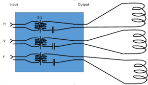
Each pair of field coils in opposite walls of a lab have box with a transformer and a resonance circuit (except for the Patient Lab). The boxes are mounted next to the door inside the lab.
The transformer and resonator box has three inputs signals (H,V and F) coming from the field amplier fed into the primary coils of three transformer that are wound 3:1. The secondary coils are connected to the field coils and have a capacitor added into the circuit in order to create a resonance condition. The capacitor are chosen in order to match the resonance frequency of the LC circuit to the frequency of the channel. These frequencies are determined by the SOM-1 sinewave generator in the Femto LIA for the corresponding channel.
The transformers consist of a ferrite ring of 21 mm diameter with 15 primary winding's and 5 secondary winding's. The winding's are made of 1.0 mm (18 AWG) coated copper wire with a current rating of 7.0 A.
Wall coils
The wall coils make up a cube of about 3 x 3 x 3 m around the subject and create low frequency magnetic fields in three orthogonal directions (Frontal, Horizontal, Vertical). The opposite wall coils are paired into one loop that create one field together.
Auditory Sphere Lab:
- two winding's per coil.
- resonator circuit.
- 3 m x 3 m coils
Auditory Motion Lab:
- two winding's per coil.
- resonator circuit.
- 3 m x 3 m coils
Auditory Perception Lab:
- five winding's per coil
- no resonator circuit.
- 2.3 m x 2.8 (2.3) m coils
Pick-up coil
There are several head mounted pick-up coils. For the Auditory Sphere Lab and the Auditory Motion Lab the coils have a flux area of 152 cm2. For the Auditory Perception Lab the flux area is 298 cm2.
- Head coil glasses Auditory Sphere Lab
- Head coil glasses Auditory Motion Lab
- Head coil glasses Auditory Perception Lab
- Test coil
ADC's
The signal coming from the output of each Lock-in amplifiers is fed into an ADC. The ADC device is optically linked to the recording device (RA16 or RZ6). The range of the ADC's is -10 V to +10 V
Auditory Sphere Lab     : RA16 with RA8GA channels 1, 2 and 3 (system 3 version)
Auditory Perception Lab : RZ6  with RA8GA channels 1, 2 and 3 (earlier version)
Auditory Motion lab     : RZ6  with RA8GA channels 1, 2 and 3 (system 3 version)
Recording device
The recording of the output of the ADC's is done by either a RA16 Madusa Base Station or a RZ6 Multi I/O processor. The ADC devices are optically linked to the recording device.
Auditory sphere lab     : RA16 on 6103.5 Hz
Auditory perception lab : RZ6 on 48828.25 Hz (divide by 10 ??)
Auditory motion lab     : RZ6 on 48828.25 Hz (divide by 10 ??)
The raw data is saved. For display a 150 Hz low pass filter is used.