Screen Trigger Device specifications: Difference between revisions
No edit summary |
|||
| (37 intermediate revisions by the same user not shown) | |||
| Line 1: | Line 1: | ||
[[File:ScreenTriggerDevicePhotograph.png|thumb|Screen trigger device]] | |||
==Description== | ==Description== | ||
The screen trigger device is a small optical sensor that can be mounted in the corner of a screen. It contains a photo diode with build in amplifier that senses the intensity of the screen locally. It has a BNC output that gives 0 Volt output when the screen is locally black and 5 V output when the screen is locally white. This can be used to create a digital timing signal for changes on the screen. | The screen trigger device is a small optical sensor that can be mounted in the corner of a screen. It contains a photo diode with build in amplifier that senses the intensity of the screen locally. It has a BNC output that gives 0 Volt output when the screen is locally black and 5 V output when the screen is locally white. This can be used to create a digital timing signal for changes on the screen. | ||
==Design== | ==Design== | ||
[[File:Screen_Trigger_Device.png | [[File:Screen_Trigger_Device.png|thumb|Screen Trigger Devices Schematics]] | ||
[[File: | [[File:Screen_Trigger_Device_with_extra_opamp.png|thumb|Adjustable Screen Trigger Device Schematics]] | ||
The screen trigger devices has a TSL25xR photo sensor with build-in amplifier | |||
The screen trigger devices has a TSL25xR photo sensor with build-in amplifier. The output current of the TSL25xR is led over a resistor in order to create a output voltage between 0 and 5V. Five devices of this simple version has been build. | |||
Two devices has been build with an extra op-amp (LM358) and a 200kOhm adjustable voltage divider. With this device the light sensitivity can be adjusted. These devices need a 9V power supply. | |||
===Components=== | |||
*Box: Hammond 1551 Series Black ABS Enclosure, IP54, Flanged, 50 x 35 x 20mm | |||
*Power supply: 5V, 2.5A, 2-Pin Type C - EuroPlug with 2.1mm DC connector | |||
*Socket: Cliff Electronic Components DC10A SOCKET, PCB, DC POWER, 2.1MM, PK10 | |||
*Photo Diode: Taos TSL25xR | |||
*Resistor: 10 kOhm | |||
==Specsheet photo diode== | |||
[[File:Sscreen Trigger Device TSL25xR specs.png|200px|Left|TSL25xR specs]] | |||
==Speed test Screen Trigger Device== | |||
A led was connected to the output of the function generator. The led was used to illuminate the photo diode. | |||
*The function generator signal is shown in yellow. | |||
*The output of the screen trigger detector is shown in red. | |||
*Risetime and falltime of the screen trigger detector is about 0.2 mSec | |||
[[File:Screen_Trigger_Device_Speed_Test.png|200px|Left|TSL25xR specs]] | |||
Latest revision as of 12:53, 8 February 2024

Description
The screen trigger device is a small optical sensor that can be mounted in the corner of a screen. It contains a photo diode with build in amplifier that senses the intensity of the screen locally. It has a BNC output that gives 0 Volt output when the screen is locally black and 5 V output when the screen is locally white. This can be used to create a digital timing signal for changes on the screen.
Design


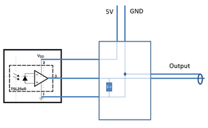
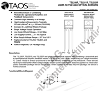
The screen trigger devices has a TSL25xR photo sensor with build-in amplifier. The output current of the TSL25xR is led over a resistor in order to create a output voltage between 0 and 5V. Five devices of this simple version has been build.
Two devices has been build with an extra op-amp (LM358) and a 200kOhm adjustable voltage divider. With this device the light sensitivity can be adjusted. These devices need a 9V power supply.
Components
- Box: Hammond 1551 Series Black ABS Enclosure, IP54, Flanged, 50 x 35 x 20mm
- Power supply: 5V, 2.5A, 2-Pin Type C - EuroPlug with 2.1mm DC connector
- Socket: Cliff Electronic Components DC10A SOCKET, PCB, DC POWER, 2.1MM, PK10
- Photo Diode: Taos TSL25xR
- Resistor: 10 kOhm
Specsheet photo diode
Speed test Screen Trigger Device
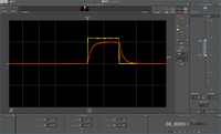
A led was connected to the output of the function generator. The led was used to illuminate the photo diode.
- The function generator signal is shown in yellow.
- The output of the screen trigger detector is shown in red.
- Risetime and falltime of the screen trigger detector is about 0.2 mSec

