TDT RZ6: Difference between revisions
| (25 intermediate revisions by the same user not shown) | |||
| Line 10: | Line 10: | ||
# '''MATLAB Integration:''' The RZ6 is fully compatible, facilitating seamless integration and data analysis within MATLAB. | # '''MATLAB Integration:''' The RZ6 is fully compatible, facilitating seamless integration and data analysis within MATLAB. | ||
# '''Reliability:''' It has a reputation for robustness and durability that students can rely on for consistent, high-quality data collection. | # '''Reliability:''' It has a reputation for robustness and durability that students can rely on for consistent, high-quality data collection. | ||
Biophysics has developed software for the RZ6 called [[BIOX]], which has an easy interface with Matlab. | |||
==Technical info== | ==Technical info== | ||
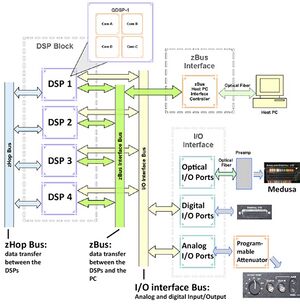
[[File: EEG_NIRS_RZ6_architecture.jpg|thumb|RZ6 architecture]] | |||
Relevant manual from TDT | |||
* Overview: https://www.tdt.com/docs/. | |||
* RZ6: https://www.tdt.com/files/manuals/hardware/RZ6.pdf. | |||
* PM2Relay: https://www.tdt.com/files/manuals/hardware/PM2R.pdf. | |||
* RPvdsEx: http://www.tdt.com/files/manuals/RPvdsEx_Manual.pdf. | |||
* ActiveX: http://www.tdt.com/files/manuals/ActiveX_User_Reference.pdf. | |||
TDT ActiveX controls enable Matlab to real-time control TDT system 3 hardware. See page 5 of the manual for example code to use Matlab to get a circuit running on the RZ6. Examples can be found in C:\TDT\ActiveX\ActXExamples\matlab. | |||
===Digital I/O=== | ===Digital I/O=== | ||
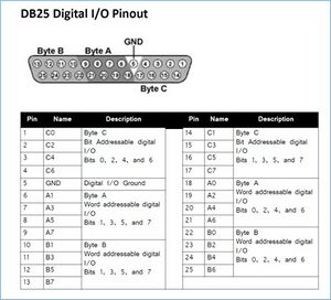
[[File: RZ6_DB25_Digital_IO_pinout.jpg|thumb|DB25 Digital I/O pinout]] | [[File: RZ6_DB25_Digital_IO_pinout.jpg|thumb|DB25 Digital I/O pinout]] | ||
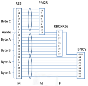
[[File: PP_RZ6_Digital_IO_connections.png|thumb|PP RZ6 Digital I/O pinout]] | [[File: PP_RZ6_Digital_IO_connections.png|thumb|PP RZ6 Digital I/O pinout]] | ||
The RZ6 has a DB25 connector for digital I/O. A custom patch panel 'PP RZ6 Digital-I/O' is available that splits the I/O to a DB25 connector for multiplexer control, a DB25 connector for a response box and eight BNC connector for separate I/O bits. | |||
====Multiplexer control==== | ====Multiplexer control==== | ||
| Line 43: | Line 54: | ||
|} | |} | ||
===Response Box=== | ====Response Box==== | ||
%todo | %todo | ||
===digital I/O=== | ====Digital I/O breakout==== | ||
The Digital I/O of the RZ6 has 24 digital lines forming byte A, B and C. For these digital lines we made a breakout panel named PP RZ6 Digital I/O. This panel has a DSub25-M connector for hooking up to the RZ6, a DSub25-M connector for connecting PM2R multiplexers to the RZ6 and a DSub25-F connector for connecting a Response Box to the RZ6. The input bits A4..A7 and output bits B4..B7 each have a BNC connector. The output bits can be used for sending trigger to other devices. The input bits can be used for receiving triggers (e.g. from a pushbutton). | |||
==Programming== | |||
===RPvdsEx=== | |||
The programming of the RZ6 is done in RPvdsEx, which is a graphical development tool by Tucker Davis Technologies. | |||
===Matlab interface=== | |||
The current (as of march 2024) Matlab interface for the TDT devices is based on the function "actxserver". Previously "actxcontrol" was used, but this will be obsolete in the near future. | |||
The following device driver functions are available in the biofysica toolbox: | |||
<pre> | |||
function [module, err, errstr] = RZ6(number,circuit) | |||
function [module, err, errstr] = ZBUS(nRacks) | |||
</pre> | |||
"Module" is an object with device specific functionality. "number" (or "nRacks") is given in order to distinguish between different hardware of the same type. "circuit" is the filename of the program that should be uploaded to the device. | |||
"err" gives an integer and "errstr" the corresponding error message. | |||
<pre> | |||
Error codes: | |||
0 ==> all devices: no error | |||
-1 ==> all devices: failed to connect | |||
-2 ==> RZ6: failed to load circuit; zBus: failed to reset | |||
-3 ==> zBus: failed to flush IO | |||
</pre> | |||
For more on the device drivers see [https://www.tdt.com/files/manuals/ActiveX_User_Reference.pdf ActiveX_User_Reference.pdf]. | |||
===BIOX toolbox=== | |||
We have developed a toolbox that can perform tasks for a large number of different experiments. It consists of RPvdsEx code for the RZ6 and a set easy to use Matlab functions. | |||
* see [[BIOX]] | |||
Latest revision as of 10:12, 13 December 2024

Description
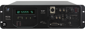
The TDT RZ6 Multi I/O Processor is an advanced research tool tailored for (PhD) students seeking versatile capabilities in neuroscience and experimental setups. This device excels in various critical aspects:
- Signal Processing Power: The RZ6 is a device, capable of real-time signal processing, making it ideal for experiments requiring precise timing and complex data manipulation.
- Multimodal Data Acquisition: It can simultaneously acquire multiple types of data, such as neural signals, analog inputs, and digital events, allowing for comprehensive experimental monitoring.
- Customizable Experimentation: The BIOX toolbox enables flexible programming for students designing and controlling experiments with a high degree of specificity.
- Synchronization: The RZ6 I/O can be used for synchronizing with other devices, ensuring precise timing between various components of an experimental setup.
- Stimulation Capabilities: Students can employ the RZ6 to deliver precisely timed stimuli, making it valuable for a wide range of experiments involving sensory or behavioral responses.
- MATLAB Integration: The RZ6 is fully compatible, facilitating seamless integration and data analysis within MATLAB.
- Reliability: It has a reputation for robustness and durability that students can rely on for consistent, high-quality data collection.
Biophysics has developed software for the RZ6 called BIOX, which has an easy interface with Matlab.
Technical info

Relevant manual from TDT
- Overview: https://www.tdt.com/docs/.
- RZ6: https://www.tdt.com/files/manuals/hardware/RZ6.pdf.
- PM2Relay: https://www.tdt.com/files/manuals/hardware/PM2R.pdf.
- RPvdsEx: http://www.tdt.com/files/manuals/RPvdsEx_Manual.pdf.
- ActiveX: http://www.tdt.com/files/manuals/ActiveX_User_Reference.pdf.
TDT ActiveX controls enable Matlab to real-time control TDT system 3 hardware. See page 5 of the manual for example code to use Matlab to get a circuit running on the RZ6. Examples can be found in C:\TDT\ActiveX\ActXExamples\matlab.
Digital I/O


The RZ6 has a DB25 connector for digital I/O. A custom patch panel 'PP RZ6 Digital-I/O' is available that splits the I/O to a DB25 connector for multiplexer control, a DB25 connector for a response box and eight BNC connector for separate I/O bits.
Multiplexer control
Byte-C is for multiplexer control. Four PM2R multiplexer can be controlled via this output. The fifth and sixth bit of byte-C codes for the PM2R device ID (0-3). The first four bits for the channel number. Only one channel can be open at a time for each PM2R. The seventh bit opens the channel and the eighth bit closes any open channel.
| Bit number | Integer value | Function |
|---|---|---|
| 0 | 1 | Bit 1 (least significant bit) of channel number |
| 1 | 2 | Bit 2 of channel number |
| 2 | 4 | Bit 3 of channel number |
| 3 | 8 | Bit 4 (most significant bit) of channel number |
| 4 | 16 | Least significant bit of device number |
| 5 | 32 | Most significant bit of device number |
| 6 | 64 | Turns on the channel of the specified device |
| 7 | 128 | Turns off all channels on the specified device only |
Response Box
%todo
Digital I/O breakout
The Digital I/O of the RZ6 has 24 digital lines forming byte A, B and C. For these digital lines we made a breakout panel named PP RZ6 Digital I/O. This panel has a DSub25-M connector for hooking up to the RZ6, a DSub25-M connector for connecting PM2R multiplexers to the RZ6 and a DSub25-F connector for connecting a Response Box to the RZ6. The input bits A4..A7 and output bits B4..B7 each have a BNC connector. The output bits can be used for sending trigger to other devices. The input bits can be used for receiving triggers (e.g. from a pushbutton).
Programming
RPvdsEx
The programming of the RZ6 is done in RPvdsEx, which is a graphical development tool by Tucker Davis Technologies.
Matlab interface
The current (as of march 2024) Matlab interface for the TDT devices is based on the function "actxserver". Previously "actxcontrol" was used, but this will be obsolete in the near future.
The following device driver functions are available in the biofysica toolbox:
function [module, err, errstr] = RZ6(number,circuit)
function [module, err, errstr] = ZBUS(nRacks)
"Module" is an object with device specific functionality. "number" (or "nRacks") is given in order to distinguish between different hardware of the same type. "circuit" is the filename of the program that should be uploaded to the device. "err" gives an integer and "errstr" the corresponding error message.
Error codes:
 0 ==> all devices: no error
-1 ==> all devices: failed to connect
-2 ==> RZ6: failed to load circuit; zBus: failed to reset
-3 ==> zBus: failed to flush IO
For more on the device drivers see ActiveX_User_Reference.pdf.
BIOX toolbox
We have developed a toolbox that can perform tasks for a large number of different experiments. It consists of RPvdsEx code for the RZ6 and a set easy to use Matlab functions.
- see BIOX