Difference between revisions of "TDT RZ6"
| Line 43: | Line 43: | ||
|} | |} | ||
| − | ===Response Box=== | + | ====Response Box==== |
%todo | %todo | ||
===digital I/O=== | ===digital I/O=== | ||
%todo | %todo | ||
Revision as of 14:49, 8 January 2024
Description
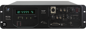
The TDT RZ6 Multi I/O Processor is an advanced research tool tailored for (PhD) students seeking versatile capabilities in neuroscience and experimental setups. This device excels in various critical aspects:
- Signal Processing Power: The RZ6 is a device, capable of real-time signal processing, making it ideal for experiments requiring precise timing and complex data manipulation.
- Multimodal Data Acquisition: It can simultaneously acquire multiple types of data, such as neural signals, analog inputs, and digital events, allowing for comprehensive experimental monitoring.
- Customizable Experimentation: The BIOX toolbox enables flexible programming for students designing and controlling experiments with a high degree of specificity.
- Synchronization: The RZ6 I/O can be used for synchronizing with other devices, ensuring precise timing between various components of an experimental setup.
- Stimulation Capabilities: Students can employ the RZ6 to deliver precisely timed stimuli, making it valuable for a wide range of experiments involving sensory or behavioral responses.
- MATLAB Integration: The RZ6 is fully compatible, facilitating seamless integration and data analysis within MATLAB.
- Reliability: It has a reputation for robustness and durability that students can rely on for consistent, high-quality data collection.
Technical info
Digital I/O
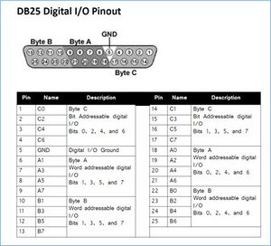
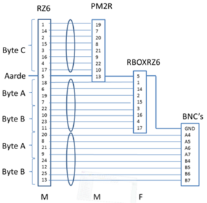
Figure 1 shows the pinout scheme of the digital I/O of the RZ6, in the lower left corner of Figure 6. Figure 13 and Figure 2 give the connection scheme of the RZ6 to the multiplexers, response box and Refa. See also Figure 10. PP refers to: “Patch Panel”, a switchboard with connectors.
Multiplexer control
Byte-C is for multiplexer control. Four PM2R multiplexer can be controlled via this output. The fifth and sixth bit of byte-C codes for the PM2R device ID (0-3). The first four bits for the channel number. Only one channel can be open at a time for each PM2R. The seventh bit opens the channel and the eighth bit closes any open channel.
| Bit number | Integer value | Function |
|---|---|---|
| 0 | 1 | Bit 1 (least significant bit) of channel number |
| 1 | 2 | Bit 2 of channel number |
| 2 | 4 | Bit 3 of channel number |
| 3 | 8 | Bit 4 (most significant bit) of channel number |
| 4 | 16 | Least significant bit of device number |
| 5 | 32 | Most significant bit of device number |
| 6 | 64 | Turns on the channel of the specified device |
| 7 | 128 | Turns off all channels on the specified device only |
Response Box
%todo
digital I/O
%todo


